Apple Internals: M1 vs M5 SecureROM, what has changed?
Introduction
Yep, we are looking at Apple now. The Windows kernel was starting to feel way too high-level: subsystems, drivers, minifilters… all of that is fine, but I want to go lower. And while thinking about what I would like to research now, what knowledge I wanted to acquire, I recalled this one topic I have been wanted to fully understand : what is the EXACT sequence that takes place in my computer when I press the power button? What code executes first? What security mechanisms are enforced before an operating system even exists?
I already had some high level overview on how this sequence takes place but still had that itch to truly understand it, instruction by instruction. I NEED TO KNOW!!!
Besides, it was the perfect excuse to dive into ARM64. ARM already dominates the mobile ecosystem and, since Apple Silicon arrived on Macs 6 years ago, it has more than proven that it can also dominate any portable device with a battery, where efficiency is key.
And why Apple? I could just as easily have gone with Windows or Linux, with their UEFI, bootloader, and all that. But once you taste the forbidden fruit, there is no going back. I think Apple Silicon is, architecturally speaking, unbeatable: Apple controls both hardware and software, integrates the Root of Trust, the Secure Enclave, and the rest of the coprocessors into the same design, and can enforce security from the very first instruction executed. Whether or not we like its ecosystem, its prices, or its philosophy… oh boy, when you look closely at the architecture and its security mechanisms, you cannot help but admire their engineering.
That is also why the Apple ecosystem is considered hard mode: proprietary hardware, closed binaries, state of the art security features and a huge amount of logic with no public documentation. Here I am interested in something slightly different from simply hunting for a vulnerability. I want to reconstruct how the platform actually works from the assembly, understand why each mechanism exists, and see how it has evolved across generations. There is a lot to explore in Apple Silicon!
But hey, less yapping and more technical content, I know this is already far too much text for any engineer.
Without further ado, let us begin this blog, in which we will dig into the first stage of Apple Silicon’s boot process: SecureROM. We will use an M1 chip to explain how it works and what it does and then compare it to an M5 version, to see what has changed over five years of Apple Silicon on Mac.
Note: This will be a dense technical analysis, with a lot of assembly dumps and theory explaining SecureROM. If you dear reader are only interested in the actual differences between generations you can jump to Conclusion (TL;DR).
The Apple Silicon boot chain
Before diving into SecureROM, it helps to keep the complete boot chain of Apple Silicon Macs in mind. The chain we will examine here applies only to Macs with M-series processors. On earlier Intel-based Macs, the process was different, and it is not relevant to this post.
Apple documents the boot process here.
Simplified, the chain is:
1
SecureROM -> LLB -> iBoot -> XNU/macOS
The chip begins by executing SecureROM, immutable code embedded in the silicon itself and the Root of Trust for the entire boot process. Its job is to establish a minimal execution state, locate an image for the next stage, and make sure it can be trusted before handing over control. If this first check fails, there is no one yet to come and fix it: all subsequent security depends on this first link working correctly.
The next stage is LLB (Low-Level Bootloader). LLB verifies and loads system-paired firmware for different internal SoC components—storage, display, system management, or Thunderbolt—and loads the LocalPolicy. The LocalPolicy is the file that specifies the rules and security level under which that Mac may boot and what software it is authorized to execute.
We distinguish three Security levels, which in short are: Full = the default state, boot only authorized software with a personalized signature; Reduced = somewhat more permissive, allowing things such as booting older versions of macOS and loading kexts (Kernel Extensions); and finally Permissive = YOLO mode (basically load whatever you want).
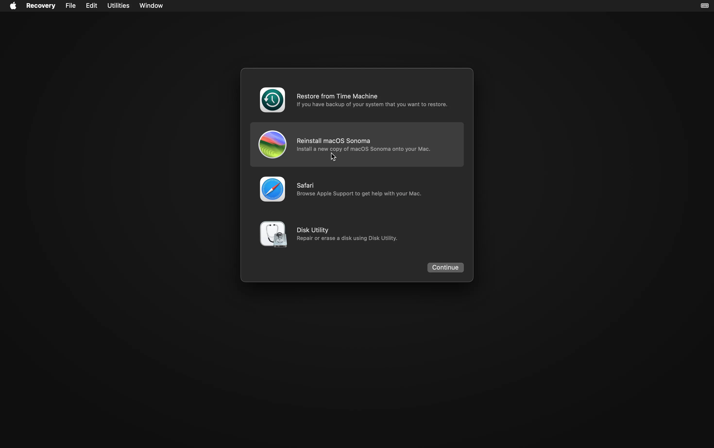
To prevent someone from restoring an older, less restrictive policy, LLB also compares its anti-replay value with the one stored in the secure storage component associated with the Secure Enclave. It then validates iBoot: using a personalized signature under Full Security or a global signature under Reduced and Permissive. A verification error redirects the boot process to recoveryOS, a secondary recovery operating system (the one you enter by holding down the power button and then selecting Options). 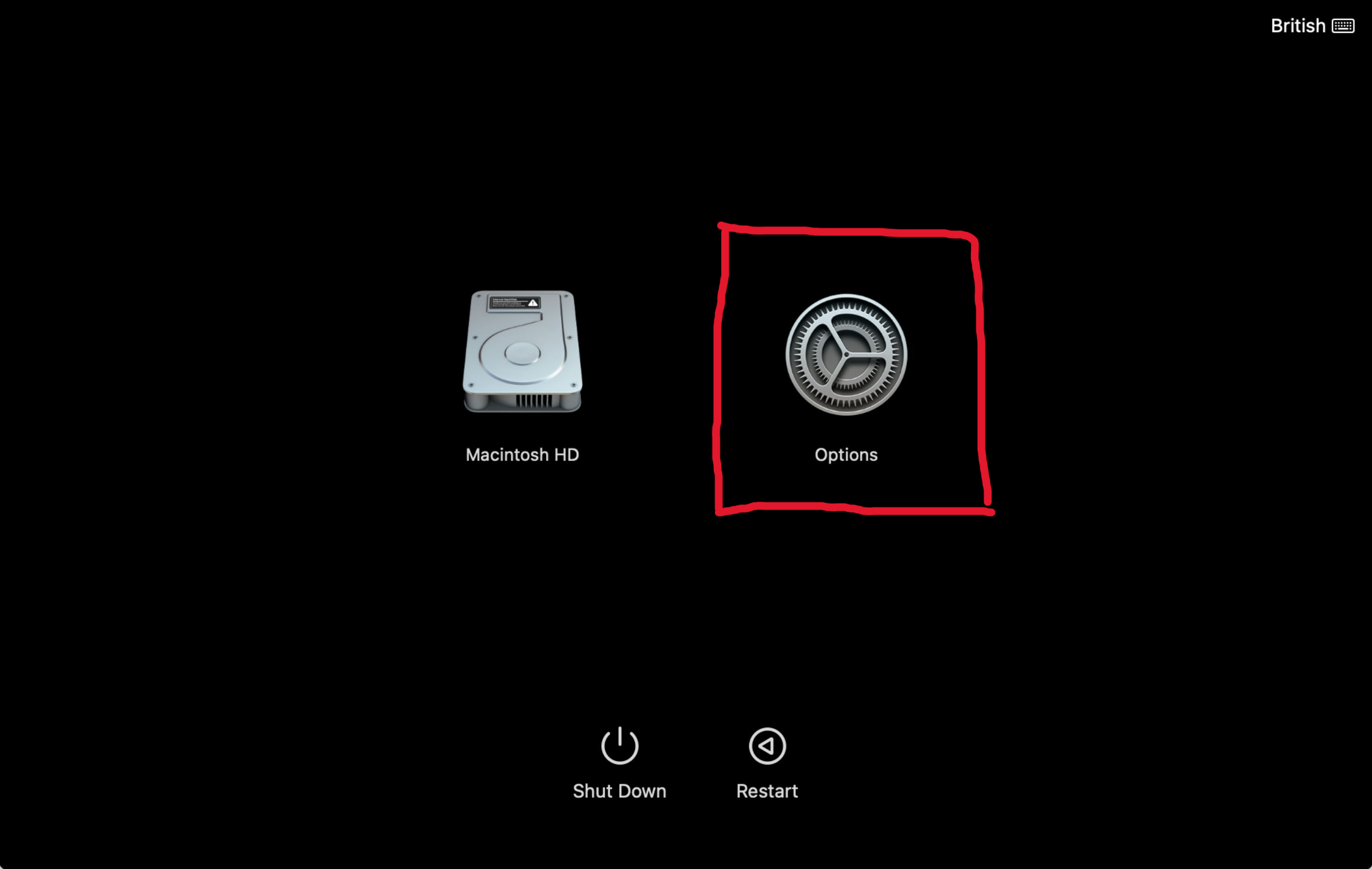
iBoot continues the chain by loading more firmware paired with macOS—for example, firmware for the Secure Neural Engine or the Always On Processor—and applies the policy received from LLB. It also validates the kernel collections, protects the memory region containing them with SCIP (System Coprocessor Integrity Protection), and checks the root hash of the Signed System Volume before finally handing control to the kernel (or to the custom boot object in the case of Permissive Security).
Before continuing, I would like to make a few notes about this particular model:
- The following chain used to apply on the M1:
1
 SecureROM -> LLB -> iBoot -> XNU/macOS
However, Apple documents SPTM support on Macs with M2 and later chips. In the M5 configuration analysed here, the chain changes slightly:
1
 SecureROM -> LLB -> iBoot -> SPTM -> XNU/macOS
On this M5 with the default LocalPolicy (Full Security), iBoot does not transfer control directly to XNU. Instead, it loads the BootKC, TXM, and SPTM images and transfers control to the latter. After setting up its own state, SPTM is the component that transfers control to XNU.
Regardless of which of the two versions presented is being used, the “core” of the boot process (the first three stages) remains the same. It is after iBoot that control is transferred to a component that may vary depending on the
LocalPolicySecurity level. Up to that point, the boot process is immutable (or at least that is the intention).- The boot model presented here was also used on iPhones with the A9 chipset or earlier. Starting with the A10 (iPhone 7), the process does away with LLB and becomes:
1
2
Up to A9: SecureROM → LLB → iBoot → XNU
From A10 onward: SecureROM → iBoot → XNU
More on this in Apple Platform Security.
Also, speaking of iPhones, they do not allow custom kernels to be loaded the way Macs do. Researchers therefore need to exploit the boot chain (or otherwise gain sufficiently early control of the device) to load and execute a custom kernel. That’s why in order to research such devices they normally need a jailbreak.
On Mac, this is not needed to load custom software, which makes projects such as Asahi Linux possible, allowing Linux to run natively on a Mac, or m1n1, a bootloader and experimentation playground that can also be used as a hypervisor beneath XNU/macOS to research and experiment with Apple’s proprietary architecture.
SecureROM Deep Dive
And so we arrive at the central topic of the blog: SecureROM.
As we have just seen, this is the first stage executed by the processor when it powers on, and it is embedded in the silicon itself. Unlike replaceable firmware such as LLB, its code cannot be modified or overwritten. In practice, the ROM contents are immutable; in theory, advanced hardware fault-injection techniques such as Laser Fault Injection could transiently alter execution, reads, or checks and allow bypasses, but they would not rewrite the ROM itself (anyways, this has not been demonstrated as far as I know).
That immutability also affects Apple: a vulnerability included in SecureROM remains in every device already manufactured and cannot be patched. One example is usbliter8, a SecureROM exploit for A12/A13.
The advantage is having a what is known as a Root of Trust: an immutable component capable of verifying the integrity of subsequent stages and preventing modifications to the boot chain, such as a malicious BootKit.
For the analysis, I will use the production M1 SecureROM (5540.0.0.400.2) as the baseline and compare it with the M5 version (10679.0.0.102.5). This M5 build is the only one I have been able to find publicly and is probably not the production version, but a beta. Even with that limitation, it will allows us to observe the important architectural changes from the M1.
The main M1 path I am going to cover is divided into three blocks:
1
2
3
4
5
6
7
8
9
10
11
12
13
14
15
16
17
18
19
20
21
22
23
24
25
26
27
28
29
30
31
32
33
34
35
36
37
38
39
40
41
42
43
44
45
46
47
48
49
50
51
52
53
54
55
56
57
58
59
60
61
62
63
64
65
66
67
68
69
70
71
72
73
74
75
76
77
78
79
80
81
82
83
84
85
86
87
88
89
90
91
92
93
94
95
96
97
98
99
100
101
102
103
104
105
106
107
108
109
110
111
112
113
114
115
116
117
118
119
120
121
122
1 — RESET AND PRE-MAIN INITIALIZATION
|
`-- SecureROM entry
    |
    +-- Prepares the privileged execution environment
    |
    +-- Initializes LLC-RAM
    |   |
    |   +-- Loads its basic configuration
    |   +-- Checks whether it is already active
    |   |
    |   +-- Yes --> continues
    |   `-- No  --> calculates the required capacity
    |               --> configures LLC-RAM
    |               --> waits until it becomes available
    |
    +-- Checks whether SecureROM is executing from the expected location
    |   |
    |   +-- Yes --> continues
    |   `-- No  --> relocates the image
    |               --> clears the previous copy
    |               --> restarts execution from the new location
    |
    +-- Installs the exception vectors
    +-- Configures the stacks
    +-- Copies the initial state into LLC-RAM
    |
    `-- Enters the early and runtime initialization phase


2 — EARLY AND RUNTIME INITIALIZATION
|
`-- Early and runtime initialization phase
    |
    +-- Early execution environment
    |   |
    |   +-- Determines the usable LLC-RAM capacity
    |   +-- Invalidates the instruction cache
    |   +-- Describes the initial memory layout
    |   +-- Builds and installs the page tables
    |   +-- Enables address translation and caches
    |   `-- Enters the unprivileged execution environment
    |
    +-- Runtime initialization
    |   |
    |   +-- Creates the main thread context
    |   +-- Initializes the event channel
    |   +-- Detects the platform and its boot configuration
    |   +-- Initializes secure dynamic memory
    |   +-- Collects entropy
    |   +-- Installs stack protections
    |   +-- Generates and enables the PAC keys
    |   +-- Prepares the code used during handoff
    |   +-- Initializes the scheduler
    |   `-- Prepares multicore control
    |
    `-- Determines how to begin the payload search
        |
        +-- Reads the physical boot configuration
        +-- Waits for possible external boot requests
        `-- Selects the first candidate


3 — PAYLOAD SELECTION, VALIDATION AND HANDOFF
|
`-- Payload loop  <------------------------------------------+
    |                                                        |
    +-- Selects a boot source                                |
    |   |                                                    |
    |   +-- Persistent storage                               |
    |   |   +-- NOR memory                                   |
    |   |   `-- SPI-NAND memory                              |
    |   |                                                    |
    |   `-- Direct transport                                 |
    |       +-- USB/DFU reception                            |
    |       `-- SoC messaging transport                      |
    |                                                        |
    +-- Prepares the buffer and resets its metadata          |
    |                                                        |
    +-- Obtains the payload                                  |
    |   |                                                    |
    |   +-- From persistent storage                          |
    |   |   `-- Locates a valid copy                         |
    |   |                                                    |
    |   `-- From a direct transport                          |
    |       `-- Receives the image into memory               |
    |                                                        |
    +-- Builds the image descriptor                          |
    |                                                        |
    +-- Validates and loads the image                        |
    |   |                                                    |
    |   +-- Checks its format and size                       |
    |   +-- Checks that the image type is accepted           |
    |   +-- Parses the container and its manifest            |
    |   +-- Applies the platform policies                    |
    |   +-- Verifies the signature and digest                |
    |   +-- Decrypts the payload when required               |
    |   +-- Extracts the payload                             |
    |   `-- Decompresses it when required                    |
    |                                                        |
    +-- Is the image valid and bootable?                     |
    |   |                                                    |
    |   +-- No                                               |
    |   |   +-- Releases the resources for this attempt      |
    |   |   +-- Clears the temporary state                   |
    |   |   `-- Is the failure terminal?                     |
    |   |       +-- Yes --> Stops the boot                   |
    |   |       `-- No  --> Selects a candidate again -------+
    |   |
    |   `-- Yes
    |       +-- Commits the authenticated boot state
    |       +-- Prepares the processors and peripherals
    |       +-- Verifies the integrity of the runtime
    |       +-- Clears SecureROM's sensitive state
    |       `-- Transfers control to the next boot stage
    |
    `-- Auxiliary services used depending on the route
        +-- USB communication
        +-- Communication between SoC components
        +-- Memory-access isolation
        +-- Cryptographic services
        `-- Timers and interrupts
The complete binary is considerably larger than this path—around 230 KB the M1 version—because it also contains numerous helpers, data sections, regions of null bytes, and auxiliary modes such as DFU that I will not cover in detail. The analysis focuses on SecureROM’s standard path.
1. RESET AND PRE-MAIN INITIALIZATION
I will present the map for each section again at the beginning of that section to orient us:
1
2
3
4
5
6
7
8
9
10
11
12
13
14
15
16
17
18
19
20
21
22
23
24
25
26
27
28
1 — RESET AND PRE-MAIN INITIALIZATION
|
`-- SecureROM entry
    |
    +-- Prepares the privileged execution environment
    |
    +-- Initializes LLC-RAM
    |   |
    |   +-- Loads its basic configuration
    |   +-- Checks whether it is already active
    |   |
    |   +-- Yes --> continues
    |   `-- No  --> calculates the required capacity
    |               --> configures LLC-RAM
    |               --> waits until it becomes available
    |
    +-- Checks whether SecureROM is executing from the expected location
    |   |
    |   +-- Yes --> continues
    |   `-- No  --> relocates the image
    |               --> clears the previous copy
    |               --> restarts execution from the new location
    |
    +-- Installs the exception vectors
    +-- Configures the stacks
    +-- Copies the initial state into LLC-RAM
    |
    `-- Enters the early and runtime initialization phase
1.1 Entrypoint
When an ARM processor comes out of reset, it does not begin by executing a main: there is no stack, virtual memory, or operating system yet. It only has the minimal state defined by the hardware and an address from which to begin execution, the reset vector.
The ARM architecture specifies that the processor enters the highest Exception Level it implements. Apple Silicon application cores do not implement architectural EL3, so the highest available level is EL2. In our dump, SecureROM’s first instruction is at 0x100000000, the address commonly used as the SecureROM base on these SoCs. Everything points to this being the address programmed into RVBAR_EL2, although the binary alone does not allow us to read the register’s physical value.
The M1 boot begins with these five instructions:
1
2
3
4
5
6
100000000  mrs  x2,hcr_el2
100000004  orr  x2,x2,#0x400000000 // E2H
100000008  orr  x2,x2,#0x8000000   // TGE
10000000c  msr  hcr_el2,x2
100000010  isb
This sequence establishes the execution model that practically the entire SecureROM runtime will use.
HCR_EL2 (Hypervisor Configuration Register) controls EL2’s behavior. SecureROM preserves its previous value (which is probably all zeros) and enables two flags: E2H and TGE.
E2H, EL2 Host, turns EL2 into a host environment. The firmware can therefore manage from EL2 the memory and exception regime used to execute code at EL0. It also changes the meaning of certain accesses to *_EL1 registers: although the assembly shows names such as VBAR_EL1, SCTLR_EL1, or TTBR0_EL1, under this configuration some of those accesses operate on host state controlled from EL2.
TGE, Traps General Exceptions, completes the model by causing relevant exceptions generated from EL0 to be handled directly by EL2 instead of passing through EL1.
To simplify, SecureROM sets up a system with two active levels from the very beginning:
1
2
3
EL2 — SecureROM host
 │
 └── EL0 — SecureROM runtime and tasks
In this way, SecureROM leaves EL1 out of the path during this stage.
Nothing has changed on the M5 yet: the sequence that configures HCR_EL2 is identical instruction for instruction. Five generations later, Apple still begins SecureROM with the same EL2/EL0 model. The first differences appear when preparing early memory.
1.2 Borrowing part of the LLC as early RAM
SecureROM is already executing instructions, but it needs writable memory in which to store its state. The code is embedded in silicon and cannot be modified, while DRAM is not yet part of a fully initialized memory environment.
Apple solves this need by reserving part of the LLC (Last Level Cache) and temporarily using it as directly addressable RAM. During early boot, that region becomes SecureROM’s private memory.
Immediately after configuring EL2, the M1 calls a function I have named init_llc_ram_and_hashes (0x100007ba8). The name is inferred—like all function names in this analysis, because SecureROM has no public symbols—but it describes the two operations visible in its assembly.
The function reads two values from what is most likely an MMIO table and writes them to two implementation-defined registers nicknamed LLC_HASH0 (S3_3_C15_C15_0) and LLC_HASH1 (S3_3_C15_C15_1). These are not part of the public ARM architecture, and Apple does not document their function. The names are inferred from their location and how the code uses them, and they match what is described in this published collection of sysregs.
1
2
3
4
5
6
7
8
9
10
11
12
13
14
; M1 - init_llc_ram_and_hashes (0x100007ba8)
100007ba8  mov   x2,#0x200000000
100007bac  ldr   w3,[x2, #offset DAT_200000008]
100007bb0  ldr   w4,[x2, #offset DAT_20000000c]
100007bb4  orr   x3,x3,x4, LSL #0x20
100007bb8  msr   sreg(0x3, 0x3, c0xf, c0xf, 0x0),x3
100007bbc  ldr   w3,[x2, #offset DAT_200000010]
100007bc0  ldr   w4,[x2, #offset DAT_200000014]
100007bc4  orr   x3,x3,x4, LSL #0x20
100007bc8  msr   sreg(0x3, 0x3, c0xf, c0xf, 0x1),x3
100007bcc  tlbi  ASIDE1IS,xzr
100007bd0  dsb   SY
100007bd4  isb
After loading them, SecureROM invalidates the corresponding translation state and synchronizes the processor.
The LLC-RAM reservation follows this flow:
1
2
3
4
5
6
7
8
9
10
11
12
13
14
15
Load the LLC hardware configuration
                │
                ▼
        Is LLC-RAM already active?
            │             │
           Yes            No
            │             │
            │             ├── Determine the block size
            │             ├── Calculate the required capacity
            │             ├── Limit it to what hardware provides
            │             └── Program the LLC-RAM partition
            │                         │
            └───────────────┬─────────┘
                            ▼
                         Continue
The configuration is controlled through another proprietary register named LLC_RAM_CONFIG (S3_3_C15_C7_0). Its fields make it possible to infer the block size, the maximum number available, and whether the partition is already active.
1
2
3
4
5
6
7
8
; M1 — get_llc_ram_size (0x100007c78)
0x100007c78  MRS  X0, S3_3_C15_C7_0  ; LLC_RAM_CONFIG
0x100007c7c  UBFX  X1, X0, #0x8, #0x6      ; block size: bits [13:8]
0x100007c80  MOV  X2, #0x1
0x100007c84  LSL   X2, X2, X1              ; 1 << block_size
0x100007c88  UBFX  X1, X0, #0x0, #0x6      ; number of blocks: bits [5:0]
0x100007c8c  MUL   X0, X1, X2              ; total LLC-RAM capacity
0x100007c90  RET
If LLC-RAM is already configured, SecureROM returns without recalculating or reprogramming the partition. It calculates how many blocks it needs only when the partition is not yet active. The amount depends on the cluster from which it is executing: on the M1, it attempts to reserve between 3.75 and 4 MiB.
SecureROM requires the hardware to provide a minimum capacity. If it cannot, SecureROM records an error and becomes trapped in an infinite loop: without early memory, it cannot build the runtime and the boot process cannot continue.
If the capacity is sufficient, it programs the partition and waits until the hardware confirms that it is active.
M5 retains this mechanism in the equivalent init_llc_ram_and_hashes function (0x100008500): it uses part of the LLC as RAM, checks whether it is already available and, when necessary, calculates its size, programs it, and waits for hardware confirmation.
The loading of LLC_HASH0 and LLC_HASH1 disappears, and M5 does not perform in this helper the translation invalidation that followed immediately afterward either. That preparation may no longer be SecureROM’s responsibility, or the LLC’s internal interface may have changed. The assembly proves that the code is gone:
1
2
3
4
5
6
7
init_llc_ram_and_hashes (M5)                  XREF[1]:   reset_entry:100000020(c)
// Skips the hash setup
100008500  mrs  x2,sreg(0x3, 0x3, c0xf, c0x7, 0x0)
100008504  and  x3,x2,#-0x8000000000000000
100008508  cbnz x3,LAB_10000859c
10000850c  ubfx x3,x2,#0x8,#0x6
M5 also reserves considerably more memory:
| Cluster | M1 | M5 |
|---|---|---|
| Main cluster | 3.75 MiB | 5.5 MiB |
| Other cluster | requests 4 MiB | may request up to 15 MiB |
In the second case, M5 attempts to obtain 15 MiB, although it accepts a reduced capacity if at least 8 MiB remains available. The increase is justified because as we will see, the new runtime uses larger structures, distributes more state within LLC-RAM, and reserves approximately twice as much space to receive the next-stage payload.
1.3 Image relocation
Once LLC-RAM is available, the M1 performs a curious check, to say the least: it calculates the address from which it is executing and compares it with the expected SecureROM base.
At a high level, the code does this:
1
2
3
4
5
if (current_base != expected_base) {
    copy_secure_rom_to_expected_base();
    erase_the_previous_copy();
    continue_execution_from_the_new_location();
}
If both addresses match—as expected on a production device—SecureROM continues directly. Otherwise, it copies the image to 0x100000000 in 16-byte blocks, jumps to the new copy, erases the previous location, and starts again from the reset vector.
It is difficult to justify this path in code embedded in silicon whose reset vector should always point to its final location. We do not know why it exists. It could come from a template shared with other bootloaders, from internal builds used during development, or from validation environments in which SecureROM was temporarily loaded at another address.
In addition, the range the routine can move is considerably larger than the useful content of the analyzed binary. This suggests that it was not written around the exact size of this image, but for a reserved region or a more generic layout.
M5 removes the entire path: it does not compare addresses, copy the code, erase a previous location, or restart execution from another base. SecureROM assumes that it is where it should be.
However, a small fossil of the previous implementation remains. M5 still calculates the current address and loads the expected base, but after initializing LLC-RAM it uses neither value. This is dead code consistent with Apple removing the relocation path as the firmware evolved.
1
2
ldr       x1,PTR_reset_entry_100000300   ; Loads the entrypoint address but
bl        init_llc_ram_and_hashes        ; never uses it
1.4 From immutable ROM to a writable runtime
Once relocation has been discarded—or completed—the M1 begins building the execution environment.
It first masks Debug, SError, IRQ, and FIQ using DAIFSet. The runtime is not yet prepared to receive asynchronous events, so interrupts remain blocked while it installs the vectors and stacks.
It then installs the exception vector table. Ghidra shows a write to VBAR_EL1, but remember that the initial HCR_EL2 configuration changes how this should be interpreted: the access is configuring the exception state used by the EL2 host. SecureROM therefore has a destination to which control can be transferred if an exception occurs.
It then prepares two stacks:
- A privileged stack for code executing at EL2.
- A stack for the runtime that will later execute tasks at EL0.
1
2
3
4
5
6
7
8
9
10
11
; M1 — reset_entry (0x100000000)
0x100000070  MSR   DAIFSet, #0xf
0x100000074  ADRP  X10, 0x100001000
0x100000078  ADD   X10, X10, #0x0
0x10000007c  MSR   VBAR_EL1, X10
0x100000080  LDR   X10, 0x100000368  ; 0x1fc031000
0x100000084  MOV   SP, X10
0x100000088  LDR   X10, 0x100000370  ; 0x1fc032000
0x10000008c  MSR   PState.SP, #0x0
0x100000090  MOV   SP, X10
0x100000094  LDR   X10, 0x100000330  ; 0x100031978
The code now has early memory, stacks, and vectors, but its initial data is still embedded in ROM and cannot be modified. To turn it into mutable state, SecureROM copies a global template into LLC-RAM:
1
2
3
4
5
6
7
8
9
10
11
12
SecureROM (immutable)
┌──────────────────────────┐
│ Code                     │
├──────────────────────────┤
│ Initial mutable template │ ───────────────┐
└──────────────────────────┘                │
                                            ▼ LLC-RAM
                                      ┌───────────┐
                                      │ globals   │
                                      │ tasks     │
                                      │ runtime   │
                                      └───────────┘
On the M1, the template occupies 0x1440 bytes, just over 5 KiB. It contains the initial state of objects that the code will modify during execution: lists, callbacks, configuration registers, task structures, memory translations, USB state, and cryptographic objects, among others.
The copy is conditional: M1 compares source and destination and skips it if the data is already in LLC-RAM. This check again suggests that the code was designed to support more than one layout, because checking for this match immediately after initializing memory adds little to a normal boot.
M5 pursues the same goal through a different bootstrap. After masking exceptions, it writes zero to another Apple implementation-defined register, SIQ_CFG_EL1 (S3_4_C15_C10_4).
The vector table remains the same: 16 entries of 0x80 bytes in a 0x800-byte table.
1
2
3
4
5
6
7
8
; M5 — reset_entry (0x100000000)
0x100000024  MSR   DAIFSet, #0xf
0x100000028  MSR   S3_4_C15_C10_4, XZR  ; SIQ_CFG_EL1
0x10000002c  ADRP  X10, 0x100021000
0x100000030  ADD   X10, X10, #0x800
0x100000034  MSR   VBAR_EL1, X10
0x100000038  LDR   X10, 0x100000348     ; 0x1fc068000
0x10000003c  LDR   X11, 0x100000350     ; 0x1fc06c000
Stack preparation does change. M1 immediately installs both the privileged stack and SP_EL0. M5 delays the operation until a second reset stage, first clears an entire 16 KiB region, and places the privileged stack at its upper end. It does not yet install a new equivalent stack for EL0.
LLC-RAM initialization also becomes more explicit. Compared with the single template of just over 5 KiB copied by M1, M5:
- Clears the region that will later be used for the page tables.
- Copies a smaller initial template of
0xd00bytes from ROM. - Clears the rest of the space reserved for mutable state.
- Separately clears the stack used during the second reset stage.
1
2
3
4
5
6
7
8
9
10
11
12
13
14
15
16
17
18
19
20
21
22
23
24
25
26
27
28
29
30
31
32
33
34
35
36
; M5 — reset_entry (0x100000000)
; Clears the 16 KiB stack used by reset_stage2.
0x100000038  LDR  X10, 0x100000348  ; 0x1fc068000
0x10000003c  LDR  X11, 0x100000350  ; 0x1fc06c000
0x100000040  STP  XZR, XZR, [X10], #0x10
0x100000044  STP  XZR, XZR, [X10], #0x10
0x100000048  CMP  X10, X11
0x10000004c  B.LT  0x100000040

; Clears the region reserved for the page tables.
0x100000050  LDR  X10, 0x100000328  ; 0x1fc004000
0x100000054  LDR  X11, 0x100000330  ; 0x1fc040000
0x100000058  STP  XZR, XZR, [X10], #0x10
0x10000005c  STP  XZR, XZR, [X10], #0x10
0x100000060  CMP  X10, X11
0x100000064  B.LT  0x100000058

; Aligns the source in ROM and copies the 0xd00-byte template.
0x100000068  LDR  X10, 0x100000310  ; 0x100053790
0x10000006c  MOV  X11, #0x3fff
0x100000070  ADD  X10, X10, X11
0x100000074  BIC  X10, X10, X11     ; source = 0x100054000
0x100000078  LDR  X11, 0x100000318  ; destination = 0x1fc040000
0x10000007c  LDR  X12, 0x100000320  ; end = 0x1fc040d00
0x100000080  LDP  X13, X14, [X10], #0x10
0x100000084  STP  X13, X14, [X11], #0x10
0x100000088  CMP  X11, X12
0x10000008c  B.LT  0x100000080

; Clears the rest of the mutable state.
0x100000090  LDR  X10, 0x100000338  ; 0x1fc040d00
0x100000094  LDR  X11, 0x100000340  ; 0x1fc051f60
0x100000098  STP  XZR, XZR, [X10], #0x10
0x10000009c  STP  XZR, XZR, [X10], #0x10
0x1000000a0  CMP  X10, X11
0x1000000a4  B.LT  0x100000098
The M5 copy always executes. It no longer compares source and destination.
At the end of this block, both chips have a privileged EL2 environment, writable LLC-RAM, exception vectors, an early stack, and a mutable copy of the initial state. M5 reaches this point without M1’s relocation path, with more LLC-RAM, a smaller data template, and explicit clearing of the regions it will use later.
2. EARLY AND RUNTIME INITIALIZATION
1
2
3
4
5
6
7
8
9
10
11
12
13
14
15
16
17
18
19
20
21
22
23
24
25
26
27
28
29
30
31
2 — EARLY AND RUNTIME INITIALIZATION
|
`-- Early and runtime initialization phase
    |
    +-- Early execution environment
    |   |
    |   +-- Determines the usable LLC-RAM capacity
    |   +-- Invalidates the instruction cache
    |   +-- Describes the initial memory layout
    |   +-- Builds and installs the page tables
    |   +-- Enables address translation and caches
    |   `-- Enters the unprivileged execution environment
    |
    +-- Runtime initialization
    |   |
    |   +-- Creates the main thread context
    |   +-- Initializes the event channel
    |   +-- Detects the platform and its boot configuration
    |   +-- Initializes secure dynamic memory
    |   +-- Collects entropy
    |   +-- Installs stack protections
    |   +-- Generates and enables the PAC keys
    |   +-- Prepares the code used during handoff
    |   +-- Initializes the scheduler
    |   `-- Prepares multicore control
    |
    `-- Determines how to begin the payload search
        |
        +-- Reads the physical boot configuration
        +-- Waits for possible external boot requests
        `-- Selects the first candidate
2.1 Early Execution Environment
SecureROM has so far executed using physical addresses; there is still no virtual address space or clear separation between code, data, MMIO, stacks, and memory intended for the next payload. This phase turns the minimal state prepared so far into a protected execution environment:
1
2
3
4
5
6
7
8
9
10
11
Physical execution in EL2
          │
          ├── Determine the available LLC-RAM
          ├── Invalidate the instruction cache
          ├── Describe the memory regions
          ├── Build the page tables
          ├── Enable the MMU and caches
          │
          ▼
SecureROM runtime initialization
in EL0 controlled by the EL2 host
The code layout changes (starting at 0x100001dd0 on the M1 versus 0x100000598 on the M5), but the logical dependencies are the same before tasks can execute at EL0.
Determine the available LLC-RAM
SecureROM has just configured the LLC-RAM partition; it now needs to know its size again in order to distribute the runtime regions. M1 reads LLC_RAM_CONFIG again and calculates:
1
LLC-RAM size = number of blocks × block size
It stores the total size and calculates how much space remains after placing the tables, global data, stacks, and the rest of the structures.
1
2
3
4
5
6
7
8
9
10
11
12
13
14
15
16
17
18
19
20
21
22
; M1 — cache_llc_ram_size (0x100008428)
0x100008434  BL    0x100007c78           ; get_llc_ram_size
0x100008438  ADRP  X8, 0x1fc021000
0x10000843c  STR   X0, [X8, #0x1c8]      ; preserves the total size

; M1 — get_llc_payload_buffer_size (0x100008448)
0x100008454  ADRP  X8, 0x1fc021000
0x100008458  LDR   X8, [X8, #0x1c8]
0x10000845c  ORR   X9, XZR, #0x1fc000000
0x100008460  ADDS  X8, X8, X9              ; end of LLC-RAM
0x100008464  B.CS  0x1000084c4             ; panic if the addition overflows

0x100008484  MOV   X9, #-0xc000
0x100008488  MOVK  X9, #0x3fb, LSL #16
0x10000848c  MOVK  X9, #0xfffe, LSL #32  ; X9 = -0x1fc04c000
0x100008490  ADD   X9, X8, X9            ; space available for the payload
0x100008494  MOV   X10, #0xfc3c0000
0x100008498  MOVK  X10, #0x1, LSL #32    ; 0x1fc04c000 + 0x374000
0x10000849c  CMP   X8, X10
0x1000084a0  MOV   W8, #0x4000
0x1000084a4  MOVK  W8, #0x37, LSL #16    ; maximum limit = 0x374000
0x1000084a8  CSEL  X0, X9, X8, CC          ; min(available, 0x374000)
M5 avoids storing the raw size first and directly calculates the usable capacity it can dedicate to the payload. After reserving what SecureROM needs, around 6.97 MiB remains, compared with 3.45 MiB on the M1: approximately twice the maximum capacity for receiving the next stage.
Cleaning the previous execution state
Before building the translation, SecureROM sets PSTATE.PAN to zero so that the privileged environment can access the space used by EL0 tasks when necessary. It also re-enables SError, which was masked during reset, now that a vector table has been installed.
It then executes the corresponding barriers and completely invalidates the instruction cache using IC IALLU. Subsequent instructions will therefore be fetched from the current image and layout, without reusing entries associated with the processor’s previous state or the M1’s possible relocation path.
1
2
3
4
5
6
7
8
9
10
11
12
13
14
15
16
17
18
19
20
21
22
; M1 - enter_el0_runtime (0x100000390)                        XREF[1]:   secure_rom_main:100001e0c(c)
100000390  pacibsp
100000394  str      x20,[sp, #-0x20]!
100000398  stp      x29,x30,[sp, #0x10]
10000039c  mov      x29,sp
1000003a0  mov      x20,x0
1000003a4  mov      x0,#0x0
1000003a8  msr      sreg(0x3, 0x0, c0x4, c0x2, 0x3),x0
1000003ac  msr      DAIFClr,#0x4
1000003b0  dsb      SY
1000003b4  isb
1000003b8  bl       invalidate_icache_all                      undefined
                                                                                 invalidate_icache_all()


                         invalidate_icache_all                     XREF[1]:   enter_el0_runtime:1000003b8(
1000004e4  ic       IALLU
1000004e8  dsb      SY
1000004ec  isb
1000004f0  ret
The operation only affects the instruction cache: it does not flush the entire cache hierarchy or erase LLC-RAM, whose data must remain intact.
The preparation is essentially the same on both chips.
Describing the memory types
Before creating the page tables, SecureROM configures the memory types in MAIR_EL1. The descriptors will later refer to the attributes defined in this register.
M1 writes MAIR_EL1 = 0x000000000000ff04, which defines two entries: Attr0 = 0x04, Device-nGnRE memory used for MMIO, and Attr1 = 0xff, normal write-back cacheable memory with read/write allocation.
1
2
3
4
5
6
7
8
; M1 — init_address_translation (0x10000cfb4)
0x10000cfe0  MOV  W0, #0xff04
0x10000cfe4  BL   0x100000464  ; write_mair_el1

; M1 — write_mair_el1 (0x100000464)
0x100000464  MSR  MAIR_EL1, X0
0x100000468  ISB
0x10000046c  RET
M5 writes MAIR_EL1 = 0x000000044401ff05 and expands the table to five entries: Attr0 = 0x05, Attr1 = 0xff, Attr2 = 0x01, Attr3 = 0x44, and Attr4 = 0x04. It retains normal write-back memory (0xff) and Device-nGnRE (0x04); 0x44 describes normal non-cacheable memory.
1
2
3
4
5
6
7
8
9
10
11
12
13
14
; M5 — construction of the MAIR_EL1 value (0x100000418)
0x100000418  MOV   X0, #0xff05
0x10000041c  MOVK  X0, #0x4401, LSL #16
0x100000420  MOVK  X0, #0x4, LSL #32  ; X0 = 0x000000044401ff05
0x100000424  RET

; M5 — build_initial_page_tables (0x10002435c)
0x10002436c  BL    0x100000418        ; obtains the value above
0x100024370  BL    0x100006c80        ; write_mair_el1

; M5 — write_mair_el1 (0x100006c80)
0x100006c80  MSR   MAIR_EL1, X0
0x100006c84  ISB
0x100006c88  RET
TCR_EL1 defines the general format of the address space: its size, page granularity, cache behavior during table walks, and the maximum physical address size. M1 writes TCR_EL1 = 0x00000001659ca51c; M5 writes TCR_EL1 = 0x0010004365d6a516.
The main properties are this:
| Property | M1 | M5 |
|---|---|---|
| Page size | 16 KiB | 16 KiB |
| Configured virtual address space | 36 bits | 42 bits |
| Configured physical address space | 36 bits | 42 bits |
Attributes defined in MAIR_EL1 | 2 | 5 |
| Pages initially reserved for tables | 3 | 15 |
The 16 KiB granularity—the standard on Apple Silicon devices—is retained, but M5 considerably expands the space it can describe and reserves five times as many pages to build its tables.
M5 also prepares top-byte handling for data addresses associated with TTBR1_EL1. Part of the upper byte can be used as metadata without participating in translation, with different handling for instruction fetches.
Building the initial page tables
SecureROM builds the tables inside LLC-RAM. The initial mappings are mostly identity mappings:
1
Virtual address == Physical address
However, the match between virtual and physical addresses does not make the MMU useless: each region can receive different attributes and permissions.
SecureROM creates separate mappings for:
- The executable SecureROM image.
- The page tables.
- Mutable global data.
- Stacks and contexts.
- Runtime structures.
- The buffer in which the payload will be received.
- The SoC’s MMIO windows.
1
2
3
4
5
6
7
8
9
10
11
12
13
14
15
16
17
18
19
20
21
22
23
24
; M1 — map_secure_rom_memory (0x1000084c8)
0x100008560  ORR   X0, XZR, #0x100000000    ; SecureROM image
0x100008564  MOV   W1, #0x2000000
0x100008568  BL    0x10000cf14
0x10000856c  BL    0x100008448              ; usable payload capacity
0x100008570  MOV   X1, X0
0x100008574  ADD   X0, X23, #0x20, LSL #12  ; buffer at 0x1fc04c000
0x100008578  BL    0x10000cf04
0x10000858c  ORR   X0, XZR, #0x200000000    ; MMIO windows
0x100008590  ORR   W1, WZR, #0x7c000000
0x100008594  BL    0x10000cf34

; M5 — map_secure_rom_memory (0x100025f80)
0x100026020  ADR   X0, 0x100000000          ; SecureROM image
0x100026024  NOP
0x100026028  BL    0x100024b90
0x10002602c  ADRP  X0, 0x1fc040000          ; mutable state
0x100026030  ADD   X0, X0, #0x0
0x100026034  MOV   X1, X20
0x100026038  BL    0x100024b7c
0x10002604c  ADRP  X0, 0x1fc04c000          ; payload buffer
0x100026050  ADD   X0, X0, #0x0
0x100026054  MOV   X1, X19
0x100026058  BL    0x100023aa4
The builder requires addresses and sizes to be correctly aligned, checks for possible overflows, and rejects incompatible descriptor combinations. If the layout cannot be represented safely, it enters the panic path (M1: 0x10000a63c; M5: 0x10000cb74). The path does not return: it records and formats the failure once the diagnostic runtime is available, executes the MMIO reset sequence, and remains halted in an infinite loop if the hardware does not complete the reset.
1
2
3
4
5
6
7
8
9
10
11
12
13
14
15
16
17
18
19
20
21
22
23
24
25
26
27
; M1 — end of panic (0x10000a63c)
0x10000a748  MOV   W0, #0x1
0x10000a74c  BL    0x10000861c        ; reset_system_and_halt

; M1 — reset_system_and_halt (0x10000861c)
0x100008628  BL    0x1000037b0        ; MMIO reset sequence
0x10000862c  B     0x10000862c        ; does not return if the reset does not complete

; M1 — trigger_system_reset (0x1000037b0)
0x1000037b0  MOV   X8, #0x10
0x1000037b4  MOVK  X8, #0x3d2b, LSL #16
0x1000037b8  MOVK  X8, #0x2, LSL #32  ; MMIO block 0x23d2b0010
0x1000037bc  STR   WZR, [X8, #0xc]
0x1000037c0  MOV   W9, #0x1
0x1000037c4  STR   W9, [X8, #0x4]
0x1000037c8  MOV   W9, #0x80000000
0x1000037cc  STR   W9, [X8]
0x1000037d0  MOV   W9, #0x4
0x1000037d4  STR   W9, [X8, #0xc]
0x1000037d8  STR   WZR, [X8]

; M5 — equivalent exit from panic (0x10000cb74)
0x10000cdc4  BL    0x10000cac4
0x10000cad0  MOV   W0, #0x1
0x10000cad4  BL    0x100009048
0x100009054  BL    0x100018960        ; MMIO reset sequence
0x100009058  B     0x100009058        ; waits indefinitely
M1 reserves three 16 KiB pages for the tables; M5 reserves fifteen, divides LLC-RAM into more regions, maintains more runtime state, and prepares translation spaces that can later be associated with different contexts.
M5’s layout defines the regions more precisely. M1 creates a 32 MiB executable mapping for SecureROM, far larger than the image’s actual size; M5 limits it to the 0x80000 bytes—512 KiB—occupied by its SecureROM.
1
2
3
4
5
M1:  [--------- 32 MiB executable window ---------]
     [actual ROM]

M5:  [actual 512 KiB ROM]
     [matching executable mapping]
M5 also leaves an unmapped page between part of the global state and the runtime’s auxiliary regions. It appears to separate the two areas so that an access that accidentally crosses the boundary generates an exception instead of immediately reaching another valid object.
The MMIO windows are also reorganized. M1 uses two large separate ranges, while M5 creates a single window covering the new peripheral map.
Enabling address translation
With the tables built, M1 installs 0x1fc000000 in TTBR0_EL1; M5 installs 0x1fc004000. They then invalidate the TLB to remove any previous translation.
M5 initializes TTBR1_EL1 to zero, although the new exception context can already restore and change it when switching between tasks. If the value changes, the runtime can also invalidate the corresponding ASID before resuming execution.
SecureROM then configures SCTLR_EL1: M1 constructs and writes 0x008d100d; M5 writes 0x0488500d.
Both values enable the MMU (M), data cache (C), instruction cache (I), stack-pointer alignment checking (SA), and WXN, which prevents writable memory from being executed. Both also retain SPAN, so an exception does not automatically force PAN = 1.
1
2
3
4
5
6
7
8
9
10
11
12
13
14
15
16
17
18
19
20
21
22
23
24
25
; M1 — enter_el0_runtime (0x100000390)
0x1000003c8  MOV  X0, XZR
0x1000003cc  ORR  X0, X0, #0x8
0x1000003d0  ORR  X0, X0, #0x1
0x1000003d4  ORR  X0, X0, #0x80000
0x1000003d8  ORR  X0, X0, #0x4
0x1000003dc  ORR  X0, X0, #0x1000
0x1000003e0  ORR  X0, X0, #0x40000
0x1000003e4  ORR  X0, X0, #0x10000
0x1000003e8  ORR  X0, X0, #0x800000  ; X0 = 0x008d100d
0x1000003ec  BL   0x100000440
0x100000440  MSR  SCTLR_EL1, X0

; M5 — reset_stage2_entry (0x100006a58)
0x100006a98  MOV  X0, XZR
0x100006a9c  ORR  X0, X0, #0x8
0x100006aa0  ORR  X0, X0, #0x1
0x100006aa4  ORR  X0, X0, #0x80000
0x100006aa8  ORR  X0, X0, #0x4
0x100006aac  ORR  X0, X0, #0x1000
0x100006ab0  ORR  X0, X0, #0x4000000
0x100006ab4  ORR  X0, X0, #0x4000
0x100006ab8  ORR  X0, X0, #0x800000  ; X0 = 0x0488500d
0x100006abc  BL   0x100006c40
0x100006c40  MSR  SCTLR_EL1, X0
The policy applied to EL0 code does change. M1 enables nTWI and nTWE, so WFI and WFE are not trapped by this control. M5 removes those two bits and enables DZE and UCI, allowing EL0 to use DC ZVA and certain cache-maintenance operations unless another EL2 control intercepts them.
1
2
3
4
5
6
7
; M1 — bits exclusive to its configuration
0x1000003e0  ORR  X0, X0, #0x40000    ; nTWE
0x1000003e4  ORR  X0, X0, #0x10000    ; nTWI

; M5 — bits that replace them in this configuration
0x100006ab0  ORR  X0, X0, #0x4000000  ; UCI
0x100006ab4  ORR  X0, X0, #0x4000     ; DZE
Entering the unprivileged runtime
To enter unprivileged execution, both versions enable FP/SIMD, allow EL0 to access the physical counter and timer, prepare a return state targeting EL0t, and execute ERET. The way they represent the destination differs.
M1 uses a fixed continuation address: after ERET, the same secure_rom_main flow continues at EL0.
1
2
3
4
5
6
; M1 — enter_el0_runtime (0x100000390)
0x100000404  MOV   X0, #0x1c0
0x100000408  MSR   SPSR_EL1, X0
0x10000040c  ADR   X0, 0x100000418  ; fixed continuation in SecureROM
0x100000410  MSR   ELR_EL1, X0
0x100000414  ERET                   ; enters EL0
M5 first builds a complete task context and restores the registers, stack, SIMD state, return address, and translation space from it. Only then does it execute ERET, entering EL0 through its scheduler’s normal mechanism.
1
2
3
4
5
6
7
8
9
10
11
12
13
14
15
16
17
18
19
; M5 — restore_exception_context_and_eret (0x1000220dc)
0x1000222a0  LDP   X0, X1, [SP, #0x100]
0x1000222a4  MSR   SPSR_EL1, X1
0x1000222a8  MSR   SP_EL0, X0
0x1000222bc  LDP   X30, X0, [SP, #0xf0]
0x1000222c0  MSR   ELR_EL1, X0
0x1000222c4  LDR   X0, [SP, #0x130]  ; TTBR1_EL1 stored in the context
0x1000222c8  MRS   X1, TTBR1_EL1
0x1000222cc  CMP   X1, X0
0x1000222d0  B.EQ  0x1000222f0
0x1000222d4  MSR   TTBR1_EL1, X0
0x1000222d8  MOV   X1, #-0x1000000000000
0x1000222dc  AND   X0, X0, X1        ; preserves the ASID
0x1000222e0  DSB   SY
0x1000222e4  TLBI  ASIDE1, X0
0x1000222e8  DSB   SY
0x1000222ec  ISB
    ; ... restores the remaining general-purpose registers ...
0x10002232c  ERET
Therefore, the difference looks something like this:
1
2
3
4
5
6
7
8
9
10
11
12
13
14
15
16
17
	 [M1]
EL2 initialization
      │
      │ ERET to a fixed continuation
      ▼
EL0 main flow


	 [M5]
EL2 initialization
      │
      ├── Build a task context
      ├── Restore its execution state
      │
      │ ERET
      ▼
EL0 main task
At the end of this phase, SecureROM has a defined address space, memory permissions, active caches, and an EL0 environment controlled from EL2. M1 enters it as the continuation of an essentially linear flow; M5 restores a task within a runtime already prepared to manage independent contexts.
2.2 Runtime initialization
The MMU and EL0 are not enough to search for and validate an image. SecureROM needs to maintain an execution context, communicate with the rest of the SoC, discover the device’s physical configuration, and have dynamic memory and secure randomness available. This phase builds that environment:
1
2
3
4
5
6
7
8
9
10
11
Unprivileged execution environment
            │
            ├── Current thread or task context
            ├── Boot event channel
            ├── Platform and boot configuration
            ├── Secure dynamic memory
            ├── Entropy and stack protections
            ├── PAC keys
            ├── Handoff support
            ├── Scheduler
            └── Multicore and interrupt control
Apple redistributes some operations between generations but preserves their dependencies: the platform must be identified and entropy must be available before generating the stack guards and PAC keys that will protect the rest of the execution.
Establishing the current execution context
M1 installs a static structure as the main thread’s context, stores its address in a global, and writes the same pointer to TPIDR_EL0. Critical sections, queues, and the scheduler can then obtain the current context by reading that register.
1
2
3
4
5
6
7
8
9
10
11
12
13
; M1 — init_thread_context (0x10000b060)
0x10000b060  ADRP  X0, 0x1fc00c000
0x10000b064  ADD   X0, X0, #0x780    ; static main-thread context
0x10000b068  B     0x10000b06c

; M1 — set_thread_context (0x10000b06c)
0x10000b06c  ADRP  X8, 0x1fc022000
0x10000b070  STR   X0, [X8, #0xde8]  ; global pointer to the current context
0x10000b074  B     0x10000c878

; M1 — write_tpidr_el0 (0x10000c878)
0x10000c878  MSR   TPIDR_EL0, X0
0x10000c87c  RET
The complete scheduler does not exist yet: only the identity of the executing flow is established here. The ordinary tasks and an idle_task will be created later.
M5 reverses the model. Before executing the main flow, it has already built the supervisor, the queues, and two 0x550-byte task contexts. It also creates a root object, prepares its stacks, and enters main by restoring one of those contexts with ERET.
That context contains the general-purpose registers, SP_EL0, ELR_EL1, SPSR_EL1, SIMD state, thread identifiers, and the associated TTBR1_EL1, not just a thread pointer. If the translation space changes, M5 invalidates the corresponding ASID before resuming the task.
1
2
3
4
5
6
7
8
9
10
11
; M5 — restore_exception_context_and_eret (0x1000220dc), compact path
0x100022118  LDP   X0, X1, [SP, #0x100]
0x10002211c  MSR   SPSR_EL1, X1
0x100022120  MSR   SP_EL0, X0
0x100022134  LDP   X30, X0, [SP, #0xf0]
0x100022138  MSR   ELR_EL1, X0
0x10002213c  LDR   X0, [SP, #0x130]
0x100022140  MRS   X1, TTBR1_EL1
0x100022144  CMP   X1, X0
0x100022148  B.EQ  0x100022168
0x10002214c  MSR   TTBR1_EL1, X0
The contrast between the two models looks like this:
1
2
3
4
5
6
7
M1: one static current-thread structure

M5: supervisor-managed task context
        ├── execution state
        ├── translation state
        ├── stack bounds
        └── security guards
Boot events and platform discovery
Before a conventional console exists, SecureROM publishes its progress through what appears to be a small four word MMIO channel: an event code and up to three arguments.
1
2
3
4
5
6
7
8
9
10
11
12
13
14
15
16
; M5 — publishing an event without arguments (0x1000085bc)
0x1000085bc  MOV   X8, #0x8030
0x1000085c0  MOVK  X8, #0x882b, LSL #16
0x1000085c4  MOVK  X8, #0x3, LSL #32  ; MMIO base = 0x3882b8030
0x1000085c8  STR   W0, [X8]           ; event code
0x1000085cc  B     0x100009c6c
0x100009c6c  STR   WZR, [X8, #0x4]    ; argument 1 = 0
0x100009c70  STR   WZR, [X8, #0x8]    ; argument 2 = 0
0x100009c74  STR   WZR, [X8, #0xc]    ; argument 3 = 0
0x100009c78  RET

; M5 — variant with three arguments (0x1000085d0)
0x1000085dc  STR   W0, [X8]
0x1000085e0  STR   W1, [X8, #0x4]
0x1000085e4  STR   W2, [X8, #0x8]
0x1000085e8  STR   W3, [X8, #0xc]
On M1, channel initialization is interleaved with preparation of the platform controllers. It configures the fabric’s minimum resources and, when finished, publishes the initial state {1, 0, 0, 0}.
M5 retains the logical format in the SoC’s new MMIO map. When a write publishes only a code, it zeroes the other three words so that arguments from the previous event are not carried over. It also publishes separate events before and after copying its version string.
SecureROM must also determine which platform it is executing on. The code initializes fabric gates and resources, applies sequences specific to the silicon revision, and configures the blocks corresponding to the current cluster. The assembly does not make it possible to identify all these proprietary controllers exactly, although it does allow the operations to be inferred:
| Class | Purpose |
|---|---|
| MMIO writes | Enable, reset, and configure SoC resources |
| MMIO reads | Obtain revision, cluster, straps, and boot requests |
| Software state | Normalize the information for subsequent decisions |
The straps are signals and physical configuration fields that describe how the machine should boot. M1 temporarily changes the mode of several fields, waits 100 microseconds, reads their values, and restores the previous configuration. From those readings, it builds a compact platform state and preserves several booleans that will determine whether it should wait for an external request or begin searching for payloads directly.
It also consumes a boot-request latch: it reads its previous state, clears the request, and publishes the corresponding acknowledgment. The previous value is preserved to select the next stage.
M5 retains the overall process with entirely different controllers, straps, and sequences, as expected for another SoC. Beyond the new addresses, it adds validations around the data obtained.
1
2
3
4
5
6
7
8
9
10
11
12
13
14
15
16
17
18
19
20
21
22
23
24
25
26
27
28
29
30
31
32
33
34
35
36
37
; M5 — validation of the identifier combination (0x10000e188)
0x10000e1b4  AND   W8, W20, #0xffff
0x10000e1b8  AND   W9, W19, #0xffff
0x10000e1bc  TST   W20, #0xff
0x10000e1c0  CSET  W10, EQ
0x10000e1c4  TST   W19, #0xff
0x10000e1c8  MOV   W11, #0xff
0x10000e1cc  CCMP  W9, W11, #0x2, NE
0x10000e1d0  CSET  W9, HI
0x10000e1d4  CMP   W8, #0xff
0x10000e1d8  CSET  W8, HI
0x10000e1dc  ORR   W9, W9, W10
0x10000e1e0  ORR   W8, W9, W8
0x10000e1e4  CMP   W0, #0x0
0x10000e1e8  CSEL  W19, W21, W8, EQ

; M5 — if validation fails, sanitizes the constructed state.
0x100000654  BL    0x10000e188
0x100000658  CBZ   W0, 0x100000678      ; accepted combination
0x10000065c  MOV   W0, #0x0
0x100000660  BL    0x1000099d0
0x100000664  MOV   X0, #0x0
0x100000668  MOV   X1, #0x0
0x10000066c  MOV   X2, #0x0
0x100000670  MOV   X3, #0x0
0x100000674  BL    0x100009788

; M5 — clears 0x380730030..0x38073005c and removes the validity marker.
0x1000097e0  ADD   X8, X19, #0x30
0x1000097e4  ADD   X9, X19, #0x5c
0x1000097e8  CMP   X8, X9
0x1000097ec  B.HI  0x1000097f8
0x1000097f0  STR   WZR, [X8], #0x4
0x1000097f4  B     0x1000097e4
0x1000097f8  LDR   W8, [X19]
0x1000097fc  AND   W8, W8, #0xffffffef  ; clears bit 4
0x100009800  STR   W8, [X19]
M5 combines platform identifiers, revision, and other silicon fields. If the combination is not acceptable, it clears part of the constructed state and removes its validity marker. M1 does not perform equivalent sanitization with the same scope before the payload loop.
Secure dynamic memory and entropy
M1 reserves a 0xc000-byte—48 KiB—arena in LLC-RAM and initializes the randomness provider on it, followed by the heap. The allocator aligns blocks to 64 bytes, maintains headers for free and allocated blocks, validates their metadata, and merges adjacent regions when they are freed.
The M1 provider checks a platform property to choose between two paths. With selector 1, it directly returns words obtained from the hardware generator. The second path implements a NIST HMAC-DRBG based on SHA-1.
M5 retains the selector and direct access to the hardware generator.
1
2
3
4
5
6
7
8
9
10
11
12
13
14
15
16
17
18
19
20
21
22
23
24
25
26
27
28
29
30
31
; M1 — init_random_provider (0x100016910)
0x10001694c  BL      0x100016a8c        ; obtains the platform selector
0x100016950  CMP     W0, #0x1
0x100016954  B.NE    0x100016968        ; selector other than 1: deterministic path
0x100016958  ADRP    X8, 0x1fc022000
0x10001695c  MOV     W9, #0x1
0x100016960  STRB    W9, [X8, #0xa41]   ; hardware provider
0x100016964  B       0x100016a44

    ; ... preparation and initialization of the deterministic path ...
0x100016a04  BLRAAZ  X8
0x100016a08  CBNZ  W0, 0x100016a7c        ; panic only if it fails
0x100016a24  MOV     W1, #0xa
0x100016a28  MOV     X3, #0x0
0x100016a2c  MOV     X4, #0x0
0x100016a30  BLRAAZ  X8
0x100016a34  STR     W20, [X19]
0x100016a38  CBNZ  W0, 0x100016a7c        ; second checked error
0x100016a3c  LDP     X1, X0, [SP, #0x8]
0x100016a40  BL      0x100016050

; The two paths converge here.
0x100016a44  MOV     W8, #0x1
0x100016a48  STRB    W8, [X21, #0xa40]  ; provider initialized
0x100016a4c  LDR     X8, [SP, #0x18]

; Common destination for failures in the alternative path.
0x100016a7c  ADR     X0, 0x100026d40
0x100016a80  NOP
0x100016a84  MOV     X1, X0
0x100016a88  BL      0x10000a63c        ; panic
Once initialized through that path, M1 generates a 16-byte seed, installs it in the global boot state, prepares the runtime metadata, and builds an auxiliary table of 256 entries.
The seed is no longer installed in the same M1 globals. M5 generates an initial 16-byte block, but no subsequent consumer appears on the analyzed path and the value is discarded. Dynamic memory no longer takes the form of the 48 KiB linear arena either: the new supervisor already has its own structures, and this phase registers ranges, prepares metadata, and marks a region as shared.
The observable behavior of each binary is:
1
2
M1: hardware RNG or HMAC-DRBG/SHA-1
M5: hardware RNG or operational CTR-DRBG/AES
Stack protections
M1 uses a global __stack_chk_guard. It attempts to fill it with eight random bytes and forces one of them to zero to make it harder for certain string-based corruptions to reproduce the full value.
The three least significant bits of the previous guard select the byte that will be set to zero. If random generation fails, it uses 0x4752400444303631 as a fallback and continues. The result is copied to __stack_chk_guard, from where it is used by functions compiled with stack protector.
1
2
3
4
5
6
7
8
9
10
11
12
13
14
15
16
17
18
19
20
21
22
23
24
25
26
27
; M1 — init_stack_canary (0x10000a7bc)
0x10000a7cc  ADRP  X19, 0x1fc021000
0x10000a7d0  ADD   X19, X19, #0x200      ; temporary guard buffer
0x10000a7d4  MOV   X0, X19
0x10000a7d8  MOV   W1, #0x8              ; requests eight random bytes
0x10000a7dc  BL    0x100016d28
0x10000a7e0  CBZ   W0, 0x10000a800       ; zero = successful generation

; Fallback when the randomness provider fails.
0x10000a7e4  MOV   X8, #0x3631
0x10000a7e8  MOVK  X8, #0x4430, LSL #16
0x10000a7ec  MOVK  X8, #0x4004, LSL #32
0x10000a7f0  MOVK  X8, #0x4752, LSL #48  ; 0x4752400444303631
0x10000a7f4  ADRP  X9, 0x1fc021000
0x10000a7f8  STR   X8, [X9, #0x200]
0x10000a7fc  B     0x10000a814

; Success: uses the previous guard to choose which byte must remain zero.
0x10000a800  ADRP  X8, 0x1fc00c000
0x10000a804  LDR   X8, [X8, #0x750]
0x10000a808  AND   X8, X8, #0x7
0x10000a80c  STRB  WZR, [X19, X8]
0x10000a810  LDR   X8, [X19]

; Publishes the final value in __stack_chk_guard.
0x10000a814  ADRP  X9, 0x1fc00c000
0x10000a818  STR   X8, [X9, #0x750]
M5 does not execute an equivalent initializer during this phase or retain that fallback. Each task contains its own guard within the context, and the supervisor installs the corresponding value in the active state each time it restores the task.
The stacks also incorporate other layers of protection:
- It initially fills them with the
stakstakpattern. - It randomly selects one of 128 possible virtual windows.
- It installs guard pages around the usable range.
- It maintains bounds associated with the context and validates them through Firebloom.
M1 also randomizes stack mappings later. M5 integrates that randomization, the guard pages, and the bounds checks directly into each task’s model.
Generating and enabling the PAC keys
The binary has already executed numerous PACIBSP and RETAB instructions, but the Pointer Authentication feature was not yet active, so those prologues had no real effect. SecureROM must generate the keys and enable SCTLR_EL1.EnIB so that they protect return addresses.
M1 generates ten 128-bit keys. Five are written to the architectural PAC registers associated with EL1, and the other five to Apple implementation-defined registers used for EL2:
| Family | Custom Apple registers |
|---|---|
| APIA | APIAKeyLo_EL2 / APIAKeyHi_EL2 (S3_6_C15_C13_0/1) |
| APIB | APIBKeyLo_EL2 / APIBKeyHi_EL2 (S3_6_C15_C13_2/3) |
| APDA | APDAKeyLo_EL2 / APDAKeyHi_EL2 (S3_6_C15_C13_4/5) |
| APDB | APDBKeyLo_EL2 / APDBKeyHi_EL2 (S3_6_C15_C13_6/7) |
| APGA | APGAKeyLo_EL2 / APGAKeyHi_EL2 (S3_6_C15_C14_0/1) |
Because the main flow is at EL0, it uses SVC #0. The handler saves the context and modifies the return state to continue temporarily in EL2t; from there, it installs the ten keys, synchronizes the processor, and clears the ten 16-byte buffers used to transport them.
It then enables bit 30, EnIB, in SCTLR_EL1 and returns to EL0. From that write onward, the PACIBSP/RETAB pairs using key B become effectively enabled.
1
2
3
4
5
6
7
8
9
10
11
12
13
14
15
16
17
18
19
; M1 — function executed before enabling EnIB.
0x100008428  PACIBSP                        ; still acts as a NOP
0x10000842c  STP      X29, X30, [SP, #-0x10]!
0x100008430  MOV      X29, SP
    ; ...
0x100008440  LDP      X29, X30, [SP], #0x10
0x100008444  RETAB                         ; return is not yet effectively authenticated

; M1 — secure_rom_main enables EnIB after installing the keys.
0x1000020b4  MOV      W0, #0x1
0x1000020b8  BL       0x1000006ec           ; set_sctlr_el1_enib

; M1 — set_sctlr_el1_enib (0x1000006ec)
0x1000006ec  MOV      X1, X0
0x1000006f0  MRS      X0, SCTLR_EL1
0x1000006f4  AND      X0, X0, #-0x40000001  ; clears EnIB
0x1000006f8  CBZ      X1, 0x100000700
0x1000006fc  ORR      X0, X0, #0x40000000   ; enables SCTLR_EL1.EnIB
0x100000700  B        0x100000440           ; writes SCTLR_EL1
M5 uses the already constructed supervisor without temporarily leaving the task model. It generates five 16-byte buffers and executes SVC #0xb to install each key. On this path, writes appear only to the five pairs of custom EL2 registers shown in the table; the five architectural EL1 pairs installed by M1 are not written.
1
2
3
4
5
6
7
8
9
10
11
12
13
14
15
16
17
18
19
20
21
22
23
24
25
26
27
28
29
30
31
32
33
34
35
36
37
38
39
40
41
42
43
44
45
46
47
48
49
; M1 — writers for the five architectural EL1 pairs.
0x100000670  MSR  S3_0_C2_C1_0, X1  ; APIAKeyLo_EL1
0x100000674  MSR  S3_0_C2_C1_1, X0  ; APIAKeyHi_EL1
0x100000684  MSR  S3_0_C2_C1_2, X1  ; APIBKeyLo_EL1
0x100000688  MSR  S3_0_C2_C1_3, X0  ; APIBKeyHi_EL1
0x100000698  MSR  S3_0_C2_C2_0, X1  ; APDAKeyLo_EL1
0x10000069c  MSR  S3_0_C2_C2_1, X0  ; APDAKeyHi_EL1
0x1000006ac  MSR  S3_0_C2_C2_2, X1  ; APDBKeyLo_EL1
0x1000006b0  MSR  S3_0_C2_C2_3, X0  ; APDBKeyHi_EL1
0x1000006c0  MSR  S3_0_C2_C3_0, X1  ; APGAKeyLo_EL1
0x1000006c4  MSR  S3_0_C2_C3_1, X0  ; APGAKeyHi_EL1

; M1 — writers for the five Apple implementation-defined pairs.
0x10000060c  MSR  S3_6_C15_C13_0, X1
0x100000610  MSR  S3_6_C15_C13_1, X0
0x100000620  MSR  S3_6_C15_C13_2, X1
0x100000624  MSR  S3_6_C15_C13_3, X0
0x100000634  MSR  S3_6_C15_C13_4, X1
0x100000638  MSR  S3_6_C15_C13_5, X0
0x100000648  MSR  S3_6_C15_C13_6, X1
0x10000064c  MSR  S3_6_C15_C13_7, X0
0x10000065c  MSR  S3_6_C15_C14_0, X1
0x100000660  MSR  S3_6_C15_C14_1, X0

; M1 — clearing one of the temporary 16-byte buffers.
0x100001fc4  ADD  X0, SP, #0x48
0x100001fc8  MOV  W2, #0x0
0x100001fcc  MOV  W1, #0x10
0x100001fd0  MOV  W3, #0x10
0x100001fd4  MOV  W4, #0x10
0x100001fd8  BL   0x1000152dc

; M5 — the selector and 128-bit key are passed to the supervisor.
0x100007118  LDP  X1, X2, [SP, #0x8]
0x10000711c  MOV  W0, #0x1
0x100007120  SVC  #0xb
    ; The remaining cases repeat the service with W0 = 2, 4, 8, and 0x10.

; M5 — the only PAC writers present use the custom EL2 pairs.
0x100006cf0  MSR  S3_6_C15_C13_0, X1
0x100006cf4  MSR  S3_6_C15_C13_1, X0
0x100006d04  MSR  S3_6_C15_C13_2, X1
0x100006d08  MSR  S3_6_C15_C13_3, X0
0x100006d18  MSR  S3_6_C15_C13_4, X1
0x100006d1c  MSR  S3_6_C15_C13_5, X0
0x100006d2c  MSR  S3_6_C15_C13_6, X1
0x100006d30  MSR  S3_6_C15_C13_7, X0
0x100006d40  MSR  S3_6_C15_C14_0, X1
0x100006d44  MSR  S3_6_C15_C14_1, X0
Each buffer is cleared immediately after the service, presumably to prevent a later read (if one could somehow occur) from recovering the keys. M5 finally executes SVC #0xa with the corresponding selector, and the supervisor enables SCTLR_EL1.EnIB.
1
2
3
4
5
6
7
8
9
10
M1
EL0 ── SVC #0 ──> temporary EL2t section
                       ├── installs 5 EL1 key pairs
                       ├── installs 5 Apple EL2 key pairs
                       └── returns to EL0

M5
EL0 task ── SVC #0xb ──> EL2 supervisor
                             ├── installs one Apple EL2 key pair
                             └── restores the task
Preparing the handoff support code
M1 prepares a small code region for the subsequent handoff to the next stage, LLB. It copies 0x400 bytes from ROM to a 16 KiB page in LLC-RAM, zeroes the rest of the page, and replaces its mapping with a specific policy.
1
2
3
4
5
6
16 KiB handoff page
┌──────────────────────┐
│ 0x400-byte code stub │
├──────────────────────┤
│ zeroed remainder     │
└──────────────────────┘
Before changing the mapping, it obtains and validates the physical address using AT S1E1R and PAR_EL1.
1
2
3
4
5
6
7
8
9
10
11
12
13
14
15
16
17
18
19
20
21
22
23
24
25
26
27
28
29
30
31
32
33
34
35
; M1 — copy_and_remap_secure_stub (0x100007ac8)
0x100007ad8  ADR   X8, 0x100009000        ; beginning of the stub in ROM
0x100007adc  NOP
0x100007ae0  ADR   X9, 0x100009400        ; exclusive end
0x100007ae4  NOP
0x100007ae8  SUBS  X19, X9, X8            ; length = 0x400
0x100007af0  ORR   X20, XZR, #0x1ffffc000
0x100007af4  MOVK  X20, #0xfc02, LSL #16  ; destination = 0x1fc02c000
0x100007af8  ADR   X1, 0x100009000
0x100007afc  NOP
0x100007b00  ORR   X0, XZR, #0x1ffffc000
0x100007b04  MOVK  X0, #0xfc02, LSL #16
0x100007b08  MOV   X2, X19
0x100007b0c  BL    0x100015e90            ; copies the 0x400 bytes

; Clears the remaining 0x3c00 bytes of the 16 KiB page.
0x100007b10  ADDS  X0, X19, X20           ; 0x1fc02c400
0x100007b18  MOV   W8, #0x4000
0x100007b1c  SUBS  X1, X8, X19            ; 0x4000 - 0x400
0x100007b24  BL    0x100007b4c

; Changes the mapping policy for the entire page.
0x100007b28  MOV   W2, #0x5
0x100007b2c  ORR   X0, XZR, #0x1ffffc000
0x100007b30  MOVK  X0, #0xfc02, LSL #16
0x100007b34  MOV   W1, #0x4000
0x100007b44  B     0x10000cf44

; M1 — address translation and validation before remapping.
0x10000054c  AT    S1E1R, X0
0x100000550  ISB
0x100000554  MRS   X1, PAR_EL1
0x100000558  TST   X1, #0x1               ; PAR_EL1 fault bit
0x10000055c  CSET  X0, EQ
0x100000560  B.NE  0x10000057c
M5 does not prepare the stub at this point in initialization, but it does retain the same overall design. The operation is postponed until SVC #7: the routine at 0x100022694 copies 0x4fc bytes from 0x100009d40 up to the exclusive limit 0x10000a23c into the 0x1fc000000-0x1fc004000 page, zeroes the rest of its 16 KiB, and configures the region through the memory subsystem.
Scheduler and task model
After installing the protections, M1 initializes the scheduler. It checks that the randomness provider is available, records a time base from the physical counter, and randomizes the stack mappings.
The runtime clears six static task slots, initializes their queues, and creates an idle_task with a minimum 16 KiB stack. It can maintain up to six ordinary tasks in addition to the special context used by the idle loop.
M5 reaches this phase with the scheduler, queues, and two fundamental contexts already built. The scheduler still depends on memory, translation, and context, but the resulting tasks have larger contexts, guard pages, Firebloom bounds, and the ability to restore their own TTBR1_EL1.
1
2
3
4
5
6
7
8
9
10
11
12
13
14
15
16
17
18
19
20
21
22
23
24
25
26
27
28
29
30
31
32
33
34
35
36
37
38
39
40
41
42
43
44
45
46
47
48
49
50
51
52
53
54
55
56
; M1 — init_idle_task_state (0x10000b078)
0x10000b094  ADRP  X0, 0x1fc00c000
0x10000b098  ADD   X0, X0, #0x930    ; fixed descriptor pool
0x10000b09c  MOV   W1, #0xa20        ; 6 * 0x1b0 bytes
0x10000b0a0  BL    0x100016050       ; clears the pool
0x10000b0a4  ADRP  X8, 0x1fc021000
0x10000b0a8  ADD   X8, X8, #0x670
0x10000b0ac  STRH  WZR, [X8, #0x4]
0x10000b0b0  STR   WZR, [X8]         ; clears all six flags
0x10000b0c0  ADRP  X0, 0x1fc021000
0x10000b0c4  ADD   X0, X0, #0x680    ; static idle_task context
0x10000b0c8  MOV   W8, #0x4000
0x10000b0cc  STR   X8, [X0, #0x190]  ; minimum stack size
0x10000b0d0  ADR   X1, 0x100026e58   ; name "idle_task"
0x10000b0d4  NOP
0x10000b0e4  BL    0x10000b114

; M1 — create_task (0x10000b35c): searches for one of the six slots.
0x10000b394  CMP   W9, #0x6
0x10000b398  B.CS  0x10000b45c
0x10000b3b4  LDRB  W10, [X8, X24]
0x10000b3b8  ADD   W9, W9, #0x1
0x10000b3bc  CBNZ  W10, 0x10000b394
0x10000b3d0  MOV   W8, #0x1b0
0x10000b3d4  MUL   X8, X24, X8            ; descriptor offset

; M5 — init_secure_runtime (0x1000260d0), first context.
0x1000263d0  ADRP  X23, 0x1fc051000
0x1000263d4  ADD   X23, X23, #0x4c0
0x1000263d8  ADD   X24, X23, #0x550
0x1000263dc  ADD   X25, X23, #0xaa0
0x1000263e0  MOV   X0, X24
0x1000263e4  MOV   X1, X24
0x1000263e8  MOV   X2, X25
0x1000263ec  BL    0x100026760       ; allocate_task_stack
0x1000263f0  MOV   X0, X24
0x1000263f4  MOV   X1, X24
0x1000263f8  MOV   X2, X25
0x100026400  BL    0x100026a24       ; initializes the task
0x10002642c  MOV   X0, X24
0x100026430  MOV   X1, X24
0x100026434  MOV   X2, X25
0x100026438  BL    0x100026ac0       ; set_thread_context

; M5 — second context and restoration that enters the first task.
0x1000264a8  MOV   X0, X23
0x1000264ac  MOV   X1, X23
0x1000264b0  MOV   X2, X24
0x1000264b4  BL    0x100026760       ; allocate_task_stack
0x1000264b8  MOV   X0, X23
0x1000264bc  MOV   X1, X23
0x1000264c0  MOV   X2, X24
0x1000264c8  BL    0x100026a24       ; initializes the task
0x1000264dc  MOV   X0, X23
0x1000264e0  BL    0x100022494       ; prepares the exception context
0x100026554  BL    0x1000220dc       ; restores the context and executes ERET
The scheduler also handles exceptions. M1 saves a 0x340-byte context when entering its handler. M5 expands it to 0x360 bytes, explicitly validates the stack pointer, and uses a common dispatcher for IRQ, FIQ, and SError. SVC64 exceptions are passed to a service dispatcher that can modify the context before restoring it with ERET.
On M5, tasks request privileged operations from the supervisor and then recover their normal context.
Multicore, timers and interrupts
Multicore control and interrupts still need to be prepared before searching for the payload.
SecureROM obtains the current cluster from MPIDR_EL1.Aff1, checks which cores are enabled, and requires the cluster from which it is executing to contain at least one. If the topology is inconsistent, it enters panic.
The topology reflected by the images changes because M5 includes more efficiency cores:
1
2
M1: 4 efficiency cores + 4 performance cores
M5: 6 efficiency cores + 4 performance cores
M1 programs the controllers for both clusters, writes 0xffffffff to 28 32-bit mask registers—covering the identifier space 0–895, up to 896 interrupt lines—and writes CNTP_CTL_EL0 = 2, leaving the physical timer disabled and its interrupt masked. It also registers two fixed groups of boot callbacks.
M5 uses a different controller and a different resource map. The physical timer had already been disabled while building the supervisor, so it does not repeat that write at the end. It also performs a preliminary query of the transport selector and enables only the resources that the observed candidate type would need.
This phase does not start any secondary core. The code checks the topology and prepares the state of the clusters, interrupt controller, and timer, but it does not install a secondary entrypoint or release another CPU from reset. The M5 supervisor’s two initial contexts do not represent two active cores either: they are software tasks that the scheduler restores on the same boot core. The remaining cores will be started at later stages of the chain.
The state available before searching for the payload is:
1
2
3
4
5
6
7
8
- A current execution context exists.
- Boot events can be published.
- The platform and boot configuration are known.
- Secure dynamic memory and entropy are available.
- Stack protections and PAC are active.
- Handoff support is prepared.
- The scheduler can manage tasks.
- Multicore and interrupt control are ready.
To recap: M1 builds a compact runtime around a main thread, a heap, and a six-slot scheduler. M5 expands that model with independent task contexts, more memory validations, guards associated with each context, and privileged services centralized at EL2.
2.3 Deciding how to begin the payload search
With the runtime prepared, SecureROM decides whether to begin searching for the payload according to the physical boot configuration or to prioritize an alternative reception or recovery path.
From the beginning of its main, M1 preserves three kinds of information: a specific strap, the state of two configuration signals, and a latch that records boot requests. If any of them already indicates a pending condition, it continues without waiting. If all of them are inactive, it opens a small window during which the external state can change.
The wait operates as a two-phase handshake:
1
2
3
4
5
6
7
8
9
10
11
12
13
14
15
16
17
18
19
Both signals inactive
        |
        v
Waits up to 6s for the first signal to become active
        |
        +-- The second signal becomes active --------> interrupts the wait
        |
        +-- The first does not activate before timeout -> normal path
        |
        `-- The first signal becomes active
                    |
                    v
          Waits up to 6s for it to become inactive again
                    |
                    +-- The second signal becomes active -> interrupts the wait
                    +-- The first becomes inactive ------> normal path
                    `-- Timeout expires -----------------> alternative path

Interval between checks: 100 ms
The second signal can interrupt either phase. The first phase’s timeout does not force the alternative path by itself: if the handshake never begins, SecureROM continues with the normal configuration. The decision changes only when the second phase expires, that is, when the first signal became active but did not return to its initial state.
Because the scheduler is already available, the pauses are not implemented with a simple busy loop. The routine schedules a timed callback for the current context and yields the task until it expires; it only resorts to busy waiting when the scheduler is not yet available.
Before making the decision, M1 registers two static groups of boot properties. The selector and the subsequent preparation of each candidate can therefore query the configuration fields through a common interface, without depending on how each strap was obtained.
The selector receives one of these two initial states:
1
2
3
4
5
6
M1
normal boot condition
    `-- begin with the candidate encoded by the physical boot configuration

alternative boot condition
    `-- begin with a direct transport candidate
The alternative condition is selected when the corresponding strap was already active or when the second phase of the handshake expires. SecureROM then publishes a specific event and uses a special initial index, which the candidate selector will interpret in the next block to choose one of the available direct transports.
M5 retains an almost identical waiting structure in its main, including the two six-second phases and the 100 ms pauses. In this build, however, it never executes it. Again, probably because this is not a release build.
M5 does not provide the same time window as M1. It combines a boot condition obtained during initialization with a subsequent validation of the physical configuration and immediately chooses between two starting points:
1
2
3
4
5
6
M5
normal boot condition
    `-- begin with the candidate encoded by the physical boot configuration

alternative boot condition
    `-- begin with the TA-DFU candidate
Both versions signal the alternative path using the same internal convention: they publish event 0x20001 and pass -1 to the selector as its initial value. Its meaning does change. On M1, it leads to one of the direct transports; on M5, it replaces the physical candidate with type 13, corresponding to TA-DFU.
This decision provides the first candidate to the payload loop.
3. PAYLOAD LOOP
1
2
3
4
5
6
7
8
9
10
11
12
13
14
15
16
17
18
19
20
21
22
23
24
25
26
27
28
29
30
31
32
33
34
35
36
37
38
39
40
41
42
43
44
45
46
47
48
49
50
51
52
53
54
55
56
57
58
59
3 — PAYLOAD SELECTION, VALIDATION AND HANDOFF
|
`-- Payload loop  <------------------------------------------+
    |                                                        |
    +-- Selects a boot source                                |
    |   |                                                    |
    |   +-- Persistent storage                               |
    |   |   +-- NOR memory                                   |
    |   |   `-- SPI-NAND memory                              |
    |   |                                                    |
    |   `-- Direct transport                                 |
    |       +-- USB/DFU reception                            |
    |       `-- SoC messaging transport                      |
    |                                                        |
    +-- Prepares the buffer and resets its metadata          |
    |                                                        |
    +-- Obtains the payload                                  |
    |   |                                                    |
    |   +-- From persistent storage                          |
    |   |   `-- Locates a valid copy                         |
    |   |                                                    |
    |   `-- From a direct transport                          |
    |       `-- Receives the image into memory               |
    |                                                        |
    +-- Builds the image descriptor                          |
    |                                                        |
    +-- Validates and loads the image                        |
    |   |                                                    |
    |   +-- Checks its format and size                       |
    |   +-- Checks that the image type is accepted           |
    |   +-- Parses the container and its manifest            |
    |   +-- Applies the platform policies                    |
    |   +-- Verifies the signature and digest                |
    |   +-- Decrypts the payload when required               |
    |   +-- Extracts the payload                             |
    |   `-- Decompresses it when required                    |
    |                                                        |
    +-- Is the image valid and bootable?                     |
    |   |                                                    |
    |   +-- No                                               |
    |   |   +-- Releases the resources for this attempt      |
    |   |   +-- Clears the temporary state                   |
    |   |   `-- Is the failure terminal?                     |
    |   |       +-- Yes --> Stops the boot                   |
    |   |       `-- No  --> Selects a candidate again -------+
    |   |
    |   `-- Yes
    |       +-- Commits the authenticated boot state
    |       +-- Prepares the processors and peripherals
    |       +-- Verifies the integrity of the runtime
    |       +-- Clears SecureROM's sensitive state
    |       `-- Transfers control to the next boot stage
    |
    `-- Auxiliary services used depending on the route
        +-- USB communication
        +-- Communication between SoC components
        +-- Memory-access isolation
        +-- Cryptographic services
        `-- Timers and interrupts
3.1 Boot source selection
The loop begins by choosing where to obtain the next payload. SecureROM has not yet read or validated any image: it combines the attempt index with the physical boot configuration and produces three internal values: a candidate type, an attribute, and a subselector that identifies its specific variant.
This candidate type identifies the backend that will provide the bytes.
The index connects this phase with the decision made at the end of the previous block:
- with the initial index
0, SecureROM follows the chip’s physical configuration; - with a nonzero index, including the special value
-1, it enters the alternative transport logic; - if an ordinary attempt fails, the index advances and the selector runs again at the beginning of the next iteration.
On M1, normal selection leads to one of the platform’s two storage sources: NOR memory or SPI-NAND. The different physical modes also determine an attribute and the controller variant that must be used.
When the index is no longer zero, the selector can replace the persistent source with one of two direct paths. One uses SecureROM’s local USB/DFU stack; the other initializes RSM and carries the communication through the SoC’s messaging mechanisms. The platform state decides which one to choose. If it requests neither, the original persistent candidate is retained.
M5 preserves the selector’s contract, but changes its set of results. The physical configuration can produce two NOR variants or a SPI-NAND source. The attribute is no longer implicit in the mode and instead comes from an independent bit in the boot configuration.
Also, during an alternative attempt, a nonzero index no longer checks a state to choose between local USB and RSM: it always forces TA-DFU. SecureROM preserves the DFU semantics visible to the host, but delegates the transport to a separate shared-memory-based service. Initialization and communication with that service take place when the loop attempts to obtain the payload.
1
2
3
4
5
6
7
8
9
10
11
12
13
14
15
16
17
18
19
20
21
22
23
24
25
26
27
28
29
30
; M1 — select_boot_transport_candidate (0x100008688)
0x1000086c4  MOV  W8, #0x1
0x1000086c8  STR  W8, [X1]     ; type 1: NOR
    ; ...
0x1000086ec  MOV  W9, #0x4
0x1000086f0  STR  W9, [X1]     ; type 4: SPI-NAND
    ; ...
0x100008730  ORR  W9, WZR, #0x6
0x100008734  B    0x100008740
0x100008738  MOV  W8, #0x0
0x10000873c  MOV  W9, #0x9
0x100008740  STR  W9, [X1]     ; direct types 6 or 9

; M5 — select_boot_transport_candidate (0x100008bc4)
0x100008c44  MOV  W8, #0x3
0x100008c48  BL   0x100009ccc  ; [X1] = 3, second NOR variant
    ; ...
0x100008c68  MOV  W8, #0x1
0x100008c6c  BL   0x100009ccc  ; [X1] = 1, first NOR variant
    ; ...
0x100008c88  MOV  W8, #0x5
0x100008c8c  BL   0x100009ccc  ; [X1] = 5, SPI-NAND
    ; ...
0x100008cb0  MOV  W8, #0xd
0x100008cb4  BL   0x100009ccc  ; [X1] = 13, TA-DFU

; M5 — common helper used by all four branches.
0x100009ccc  STR  W8, [X1]
0x100009cd0  CMP  X11, X10
0x100009cd4  RET
| Selected source | M1 | M5 |
|---|---|---|
| NOR | type 1 | types 1 and 3, two nor0 variants |
| SPI-NAND | type 4 | type 5 |
| Direct transport | types 6 and 9: local USB/DFU or RSM | type 13: TA-DFU |
| Additional path present but not emitted by the selector | type 10 | no equivalent direct path |
The effective paths are:
1
2
3
4
5
6
7
8
9
10
11
12
13
14
15
16
17
18
19
20
21
M1
physical boot configuration
        |
        `-- NOR or SPI-NAND
                    |
                    `-- failed attempt
                              |
                              `-- run the selector again
                                      |
                                      +-- local USB/DFU or RSM,
                                      |   when requested by the platform
                                      `-- otherwise keep the persistent source

M5
physical boot configuration
        |
        `-- NOR or SPI-NAND
                    |
                    `-- failed attempt
                              |
                              `-- TA-DFU
If the selector cannot produce a valid candidate, SecureROM records the failure and stops the boot through the reset/halt path. On M1, this happens when the physical value falls outside the eight supported modes. On M5, whose selector uses a three-bit field, one of the eight combinations is reserved and likewise produces no candidate during normal selection.
3.2 Preparing the payload buffer and resetting its metadata
Once the candidate has been selected, SecureROM prepares the attempt’s LLC-RAM region. It rebuilds the boot state, clears the entire payload space, and records its bounds again before accessing the chosen source.
Both versions start from the actual end of the available LLC-RAM, subtract the area occupied by the runtime, and cap the result to a maximum window:
| M1 | M5 | |
|---|---|---|
| Buffer start | 0x1fc04c000 | 0x1fc088000 |
| Maximum capacity | 0x374000 bytes | 0x6f8000 bytes |
| Maximum end | 0x1fc3c0000 | 0x1fc780000 |
The calculation can be expressed as follows:
1
usable capacity = min(LLC-RAM end - payload buffer start, maximum window)
The code checks that the addition used to obtain the end of LLC-RAM does not overflow and that space exists beyond the beginning of the buffer. An impossible layout is treated as corruption of the platform state and ends in panic.
1
2
3
4
5
6
7
8
9
10
11
12
13
14
15
16
17
18
19
20
21
22
23
24
25
; M1 — get_llc_payload_buffer_size (0x100008448)
0x100008484  MOV   X9, #-0xc000
0x100008488  MOVK  X9, #0x3fb, LSL #16
0x10000848c  MOVK  X9, #0xfffe, LSL #32  ; -0x1fc04c000
0x100008490  ADD   X9, X8, X9            ; LLC_end - payload_start
0x100008494  MOV   X10, #0xfc3c0000
0x100008498  MOVK  X10, #0x1, LSL #32    ; end of the 0x374000-byte maximum
0x10000849c  CMP   X8, X10
0x1000084a0  MOV   W8, #0x4000
0x1000084a4  MOVK  W8, #0x37, LSL #16    ; 0x374000
0x1000084a8  CSEL  X0, X9, X8, CC         ; min(available, 0x374000)

; M5 — FUN_100007df0 (0x100007df0)
0x100007e3c  MOV   W0, #0x8000
0x100007e40  MOVK  W0, #0x6f, LSL #16    ; initial limit = 0x6f8000
0x100007e44  STR   X0, [X19, #0x8e8]
0x100007e48  ORR   X9, XZR, #0x1ffffffff
0x100007e4c  MOVK  X9, #0xfc77, LSL #16  ; 0x1fc780000 - 1
0x100007e50  CMP   X8, X9
0x100007e54  B.HI  0x100007e6c            ; keeps the maximum
0x100007e58  MOV   X9, #-0x8000
0x100007e5c  MOVK  X9, #0x3f7, LSL #16
0x100007e60  MOVK  X9, #0xfffe, LSL #32  ; -0x1fc088000
0x100007e64  ADD   X0, X8, X9            ; LLC_end - payload_start
0x100007e68  STR   X0, [X19, #0x8e8]     ; caches the calculated capacity
M5’s window is approximately twice as large as M1’s. M5 stores the calculated capacity the first time, so subsequent queries reuse the value. Both the routine that rebuilds the metadata and main itself request that capacity during the same attempt.
Preparing the candidate-specific platform state
Some candidates require several platform fields to be programmed temporarily. They are not image data: they prepare the state required for the selected source and are restored when the attempt ends.
M1 contains two tables:
- The type
1NOR path uses fields0x502-0x505. When it is activated, three are programmed with mode5and field0x505with mode3; when the candidate is cleared, all four return to mode4. - The type
4SPI-NAND path uses0x803-0x805. Its three entries specify mode4both on entry and on exit.
1
2
3
4
5
6
7
8
9
10
11
12
13
14
15
16
17
18
19
20
; M1 — tables read by configure_candidate_register_fields (0x1000087bc).
; Each entry is {field, value on activation, value on clearing}.
0x1000297d0  .word  0x505, 0x3, 0x4
0x1000297dc  .word  0x502, 0x5, 0x4
0x1000297e8  .word  0x503, 0x5, 0x4
0x1000297f4  .word  0x504, 0x5, 0x4       ; type 1: four entries

0x100029800  .word  0x803, 0x4, 0x4
0x10002980c  .word  0x804, 0x4, 0x4
0x100029818  .word  0x805, 0x4, 0x4       ; type 4: three entries

; M1 — table selection according to the candidate type.
0x100008800  ADR  X8, 0x100029800   ; type 4 table
0x100008808  ORR  W9, WZR, #0x3     ; three entries
0x100008820  ADR  X13, 0x1000297d0  ; type 1 table
0x10000882c  LSL   W11, W11, #0x2         ; four entries if W2 == 1
0x100008840  CMP  W1, #0x4
0x100008844  CSEL  X22, X10, X12, EQ
0x100008848  CSEL  X23, X8, X13, EQ
0x10000884c  CSEL  W24, W9, W11, EQ
M5 expands the tables for its new variants:
- Type
1NOR uses0x403-0x406and0x600-0x601. The central fields are activated with mode6and the remaining ones with mode3; all are restored to mode4. - Type
3NOR uses the same six fields, but activates them with mode7before restoring them to mode4. - Type
5SPI-NAND uses0x407,0x500, and0x501, all with mode4. - TA-DFU, type
13, has no entries in these tables and this function does not modify fields for that candidate.
1
2
3
4
5
6
7
8
9
10
11
12
13
14
15
16
17
18
19
20
21
22
23
24
25
26
27
28
29
; M5 — type 1, subselector 1: six entries.
0x10004a358  .word  0x403, 0x3, 0x4
0x10004a364  .word  0x404, 0x6, 0x4
0x10004a370  .word  0x405, 0x6, 0x4
0x10004a37c  .word  0x406, 0x6, 0x4
0x10004a388  .word  0x601, 0x3, 0x4
0x10004a394  .word  0x600, 0x3, 0x4

; M5 — type 3, subselector 10: the same fields with mode 7.
0x10004a3a0  .word  0x403, 0x7, 0x4
0x10004a3ac  .word  0x404, 0x7, 0x4
0x10004a3b8  .word  0x405, 0x7, 0x4
0x10004a3c4  .word  0x406, 0x7, 0x4
0x10004a3d0  .word  0x601, 0x7, 0x4
0x10004a3dc  .word  0x600, 0x7, 0x4

; M5 — type 5: three entries with no mode change between activation and clearing.
0x10004a3e8  .word  0x407, 0x4, 0x4
0x10004a3f4  .word  0x500, 0x4, 0x4
0x10004a400  .word  0x501, 0x4, 0x4

; M5 — configure_candidate_register_fields (0x1000090ec)
0x100009140  ADR  X8, 0x10004a3a0   ; type 3 table
0x100009148  ADD  X9, X8, #0x48
0x100009160  ADR  X11, 0x10004a358  ; type 1 table
0x100009168  ADD  X12, X11, #0x48
0x1000091a0  ADR  X23, 0x10004a3e8  ; type 5 table
0x1000091a8  ADD  X22, X23, #0x24
0x1000091ac  MOV  W8, #0x3
In both generations, activation walks the table in reverse order and clearing walks it in forward order. M5 also associates an explicit span with each table: an overflow or an out-of-bounds access ends in the Firebloom handlers. M1 also stops execution under those conditions, although it uses fixed checks on indices, offsets, and sizes that end in BRK or panic, instead of M5’s span model.
Rebuilding the boot metadata
Each attempt rebuilds a small block that describes the boot state. M1 starts with the word 0x202c0000 and adds flags derived from the platform, board, and several features. If available, it copies an optional 0x30-byte block and marks its presence. The two control fields are initialized to -1 and 0.
M5 uses an equivalent structure at a different location that starts with 0x222c0000. It retains the main platform and board flags and also initializes the control fields to -1 and 0, but this function no longer copies the optional 0x30-byte block present on M1.
The entire buffer capacity is then cleared. The code can split very large operations into chunks of up to 0x10000000 bytes and clears the state associated with the payload stream before each one. The maximum M1 and M5 windows, however, fit in a single chunk.
M1 performs the clearing through its normal zeroing primitive. M5 also passes the beginning, end, and authorized span to a bounds-checked primitive; overflows and out-of-range accesses converge on the arithmetic or Firebloom panics. Afterwards, both versions record the entire region as a range reserved for the payload.
The order of operations changes slightly:
1
2
3
4
5
6
7
8
9
M1
calculate capacity
    `-- configure candidate fields
            `-- rebuild metadata and clear the buffer

M5
rebuild metadata and clear the buffer
    `-- reuse the cached capacity
            `-- configure candidate fields
Each candidate reaches the acquisition stage with a window sized for its SoC, consistent metadata, and no residual bytes from the previous attempt.
3.3 Obtaining the payload
Acquisition depends on the candidate. Persistent paths turn a physical device into a readable source and locate the firmware copy to use within it; direct paths receive the complete bytes in the LLC-RAM buffer prepared earlier.
Reading from persistent storage
As we have seen, M1 implements two persistent backends. Type 1 initializes NOR memory and registers the nor0 source. The routine configures the SPI channel, adapts its frequency to the boot mode, and polls the NOR status register with command 0x05 until the device is no longer busy. The wait is limited to 50,000 µs. If initialization completes successfully, nor0 is exposed as a 0x400000-byte source with 0x1000-byte blocks.
Type 4 builds the spi_nand0 source, whose capacity is not fixed in advance. After preparing the signals and the SPI channel, it sends two queries to obtain the device geometry. Each response must contain the 0x55aa5500 signature, a valid status, and the requested value. From those results, SecureROM calculates the number of available blocks and registers the source with 0x1000-byte blocks.
1
2
3
4
5
6
7
8
9
10
11
12
13
14
15
16
; M1 — SPI-NAND response validation (0x10000fccc)
0x10000fd70  LDRB  W8, [SP, #0x4]
0x10000fd74  LSL   W9, W8, #0x18
0x10000fd78  LDRB  W8, [SP, #0x5]
0x10000fd7c  BFM   W9, W8, #0x10, #0x7
0x10000fd80  LDRB  W8, [SP, #0x6]
0x10000fd84  BFM   W9, W8, #0x18, #0x7
0x10000fd88  LDRB  W8, [SP, #0x7]         ; status byte
    ; ... separate handling of the 0xffffffff response ...
0x10000fdb0  MOV   W10, #0x5500
0x10000fdb4  MOVK  W10, #0x55aa, LSL #16  ; signature = 0x55aa5500
0x10000fdb8  CMP   W9, W10
0x10000fdbc  B.NE  0x10000fde8            ; incorrect signature
0x10000fdc0  CMP   W8, #0x0
0x10000fdc4  CSETM W0, NE                 ; propagates an invalid status
0x10000fdcc  CBNZ  W8, 0x10000fdec
The routines do not return the firmware directly. They create a descriptor containing the source’s name, size, block size, context, and read callbacks. Later code can therefore handle nor0 and spi_nand0 through the same interface, even though their physical operations differ.
M5 preserves the names and equivalent functions, but redistributes the types. Candidates 1 and 3 end up at nor0: the first uses subselector 1 and the second uses 10, with different initialization parameters. main explicitly checks both combinations and considers any other variant of those paths impossible.
SPI-NAND moves to type 5 and retains subselector zero. Initialization is stricter than on M1: it expects the 0x55aa5508 signature and adds a test with the 0b aa cc bb sequence. The response must reproduce the expected pattern before spi_nand0 is registered. All temporary buffers, responses, and driver structures carry their spans; an access outside them ends in panic.
1
2
3
4
5
6
7
8
9
10
11
12
13
14
15
16
17
18
19
20
21
22
23
24
25
26
27
28
29
30
31
32
; M5 — init_spi_nand_storage_source (0x1000193a8)
0x10001950c  MOV   W26, #0x5508
0x100019510  MOVK  W26, #0x55aa, LSL #16  ; W26 = 0x55aa5508
0x100019514  LDR   W8, [SP, #0x1c]
0x100019518  CMP   W8, W26
0x10001951c  B.NE  0x1000195dc

; Builds the 0b aa cc bb sequence on the stack.
0x100019520  MOV   W8, #0xb
0x100019524  STP   WZR, W8, [SP, #0x28]
0x100019528  ADD   X10, SP, #0x2c
0x100019530  ORR   X8, X10, #0x1
0x100019540  MOV   W9, #0xaa
0x100019544  STRB  W9, [X8]
0x100019548  ORR   X9, X10, #0x2
0x100019558  MOV   W10, #0xcc
0x10001955c  STRB  W10, [X9]
0x100019560  ADD   X11, SP, #0x2c
0x100019564  ORR   X10, X11, #0x3
0x100019574  MOV   W24, #0xbb
0x100019578  STRB  W24, [X10]

    ; Performs the exchange and compares the response with the expected pattern.
0x1000195b4  BL    0x100019c20
0x1000195b8  TBNZ  W0, #0x1f, 0x1000196a4
0x1000195bc  LSL   W8, W27, #0x10
0x1000195c0  BFM   W8, W25, #0x8, #0x7
0x1000195c4  BFM   W8, W26, #0x18, #0x7
0x1000195c8  ORR   W8, W8, W24
0x1000195cc  LDR   W9, [SP, #0x28]
0x1000195d0  CMP   W9, W8
0x1000195d4  B.NE  0x1000196a4
Locating a valid firmware copy
Once the device has been registered, SecureROM looks up the source by name and uses the same resolver for NOR and SPI-NAND. Since storage does not necessarily contain a single image at a fixed offset, it first examines a small selection area made up of HUFA headers.
M1 tries up to 32 positions separated by 0x1000-byte blocks, from offset 0 through 0x1f000. At each position:
- it checks the
HUFAmagic and requires version1; - it reads the full header again;
- it calculates SHA-384 over its first
0x20bytes and compares the0x20bytes stored as the digest; - if the header is valid, it keeps its generation counter and the offset associated with the image.
The scan stops after checking all 32 positions or as soon as it finds two valid copies. If only one valid copy is found, SecureROM uses it. If it finds two, it selects the one with the higher unsigned generation counter; in the event of a tie, it keeps the first.
1
2
3
4
5
6
7
8
9
10
11
12
13
14
15
16
17
18
19
20
21
22
23
24
25
26
27
28
29
30
31
32
33
34
35
36
37
38
39
40
41
42
43
44
45
46
47
48
49
; M1 — select_hufa_firmware_offset (0x100019d10)
0x100019d54  MOV     W26, #0x5548
0x100019d58  MOVK    W26, #0x4146, LSL #16    ; W26 = 0x41465548 ("HUFA")
0x100019d68  CMP     W25, #0x1f               ; at most 32 positions
0x100019d6c  B.HI  0x100019ed4
0x100019d70  LDR     X8, [X20, #0x28]
0x100019d7c  MOV     X0, X20
0x100019d80  MOV     X1, X22
0x100019d84  MOV     X2, X21                  ; current offset
0x100019d88  MOV     W3, #0x4
0x100019d8c  BLRAAZ  X8
0x100019d90  CMP     W0, #0x4
0x100019d94  B.NE    0x100019e2c
0x100019d98  LDR     W1, [X22]
0x100019d9c  CMP     W1, W26                  ; checks the HUFA magic
0x100019da0  B.NE    0x100019e50

0x100019da4  LDR     X8, [X20, #0x28]
0x100019da8  MOV     X0, X20
0x100019dac  MOV     X1, X22
0x100019db0  MOV     X2, X21
0x100019db4  MOV     W3, #0x40                ; reads the full header again
0x100019db8  BLRAAZ  X8
0x100019dbc  CMP     W0, #0x40
0x100019dc0  B.NE    0x100019e58
0x100019dc4  LDR     W1, [X22]
0x100019dc8  CMP     W1, W26
0x100019dcc  B.NE    0x100019e78
0x100019dd4  LDR     W1, [X23, #0x4]
0x100019dd8  CMP     W1, #0x1                 ; supported version
0x100019ddc  B.NE    0x100019ea4

0x100019dec  MOV     X2, SP
0x100019df0  MOV     X0, X22
0x100019df4  MOV     W1, #0x20
0x100019df8  ORR     W3, WZR, #0x30
0x100019dfc  BL      0x10000a8a0              ; calculates SHA-384
0x100019e00  ADD     X1, X23, #0x20
0x100019e04  MOV     X0, SP
0x100019e08  MOV     W2, #0x20
0x100019e0c  BL      0x100016198              ; compares the stored digest
0x100019e10  CBZ     W0, 0x100019ec4

0x100019e98  ADD     X21, X21, #0x1, LSL #12  ; next 0x1000-byte block
0x100019e9c  ADD     W25, W25, #0x1
0x100019ea0  B       0x100019d68
0x100019ec4  ADD     W19, W19, #0x1           ; valid header
0x100019ec8  CMP     W19, #0x2
0x100019ecc  B.NE    0x100019e98              ; stops after finding two
The absence of a valid HUFA header does not immediately cause the candidate to fail. The resolver returns offset zero and attempts to interpret an image from the beginning of the source.
M5 preserves the HUFA format, the maximum of 32 positions, the selection between up to two copies, and the same error events. It changes the representation of the parameters, not the persistent format: the source, header, reads, and results carry explicit bounds that are validated before each access.
Receiving from a direct transport
On M1, types 6, 9, and 10 converge on the same reception routine. Types 6 and 9 use the first group of callbacks; type 9 also initializes the RSM backend before starting and always tears it down when finished, even if reception fails.
The active path gives the transport the beginning of the payload buffer and its full capacity. If the USB/DFU operation is asynchronous, it marks reception as active and blocks the current task on an event. There is no additional timeout in this loop: the transport callback changes the completion state and wakes the task.
On the local USB path, SecureROM directly controls the DWC2 device, its endpoints, and the DMA buffers, whose access it restricts through DART/IOMMU. With type 9, RSM adds communication between SoC components: it configures its MMIO region and interrupt, creates a dedicated task, and moves messages through rings and hardware notifications. A bridge connects those messages to the logical interface of the DFU stack.
When finished, the routine stops the transport and returns a signed length. A negative result abandons acquisition; a length greater than the buffer capacity is considered a fatal inconsistency. A zero length is still accepted at this point although the following layers may reject it.
M5 removes the local DWC2 stack and the RSM backend from the main flow. The type 13 direct candidate calls receive_payload_via_ta_dfu_transport (0x10001ffb4) and delegates reception to the ta_dfu service through a shared-memory region.
SecureROM registers the service and the shared region, creates the necessary event objects, and installs the shared interrupt handler. It then builds a 0x3c0-byte Apple DFU block containing the USB identifiers, revision, device name, serial, SRTG, nonces, and any available optional data. When it publishes the block to the shared interface, the 0x61444655 magic seems to tell the other component that it may begin.
The task waits until the ta_dfu interrupt indicates that reception has finished. The handler acknowledges and confirms the cause, updates the shared state, and wakes the wait object. Before returning, the function disables the backend and clears the registrations, callbacks, and objects created for the exchange.
1
2
3
4
5
6
7
8
9
10
11
12
13
14
15
16
17
18
19
20
21
22
23
24
25
26
27
; M5 — receive_payload_via_ta_dfu_transport (0x10001ffb4): publication
0x100020184  MOV   W0, #0x0
0x100020188  BL    0x100034790
0x10002018c  MOV   W1, #0x1
0x100020190  MOV   W2, #0x3c0            ; size of the Apple DFU block
0x100020194  BL    0x10003473c
    ; ... fills in identifiers, revision, serial, SRTG, and nonces ...
0x10002033c  MOV   X0, X19
0x100020340  MOV   X1, X21
0x100020344  MOV   X2, X22
0x100020348  MOV   X3, X20
0x10002034c  BL    0x100022d38           ; publishes the block to the shared region
0x100020350  MOV   W20, #0x1
0x100020354  MOV   W0, #0x1
0x100020358  BL    0x1000206e8           ; enables the backend
0x10002035c  MOV   W0, #0x0
0x100020360  MOV   W1, #0x4655
0x100020364  MOVK  W1, #0x6144, LSL #16  ; W1 = 0x61444655
0x100020368  BL    0x10000dde0

; Waits until the handler marks reception as complete.
0x100020398  LDRB  W8, [X20, #0x861]
0x10002039c  TBNZ  W8, #0x0, 0x1000203b0
0x1000203a0  LDP   X0, X1, [X21]
0x1000203a4  LDP   X2, X3, [X21, #0x10]
0x1000203a8  BL    0x10002de50           ; waits on the event
0x1000203ac  B     0x100020398
1
2
3
4
5
6
7
8
9
10
11
12
13
14
15
16
17
18
19
; M5 — TA-DFU interrupt handler (0x100020548)
0x1000205bc  MOV   W0, #0x864
0x1000205c0  BL    0x10000dd80  ; reads the pending causes
    ; ... acknowledges and confirms the active causes ...
0x10002060c  TBZ   W19, #0x0, 0x100020648
0x100020610  LDRB  W8, [SP, #0x8]
0x100020614  TBZ   W8, #0x3, 0x100020648
0x100020618  MOV   W0, #0xc
0x10002061c  BL    0x10000de18
0x100020620  LDRB  W8, [X24, #0x861]
0x100020624  TBNZ  W8, #0x0, 0x100020648
0x100020628  CBZ   W0, 0x100020648
0x10002062c  STUR  W0, [X25, #0xb]         ; stores the result
0x100020630  STRB  W26, [X25]   ; marks completion
0x100020634  LDUR  X0, [X25, #0x57]
0x100020638  LDUR  X1, [X25, #0x5f]
0x10002063c  LDUR  X2, [X25, #0x67]
0x100020640  LDUR  X3, [X25, #0x6f]
0x100020644  BL    0x10002de18  ; wakes the wait object
1
2
3
4
5
6
7
8
9
10
11
12
13
14
15
16
17
18
19
20
; M5 — receive_payload_via_ta_dfu_transport (0x10001ffb4): cleanup
0x1000203bc  MOV   W0, #0x0
0x1000203c0  BL    0x10000ddb0
0x1000203c4  MOV   W0, #0x0
0x1000203c8  MOV   W1, #0x0
0x1000203cc  BL    0x10000dde0
    ; ... clears the published fields through all 0x3c0 bytes ...
0x100020418  MOV   X19, #-0x3c0
0x10002041c  CBZ   X19, 0x100020434
0x100020420  ADD   W0, W19, #0x400
0x100020424  MOV   W1, #0x0
0x100020428  BL    0x10000dde0
0x10002042c  ADD   X19, X19, #0x4
0x100020430  CBNZ  X19, 0x100020420
0x100020434  MOV   W0, #0x0
0x100020438  BL    0x1000206e8  ; disables the backend
0x100020448  STRB  WZR, [X28]
    ; ... destroys callbacks, events, and temporary registrations ...
0x100020488  BL    0x10000e00c
0x10002048c  STRB  WZR, [X28, #0x2]
3.4 Building the image descriptor
SecureROM does not give the validator a raw pointer to the payload. It builds an object that indicates how to access it, how large it is, what kind of source it comes from, and which flags must be applied. The direct and persistent paths use different representations, although both expose a common header to the loader:
1
2
3
4
+0x0  payload length
+0x4  image type
+0x8  source magic
+0xc  validation flags
The magic distinguishes bytes that are already in memory from those that still need to be read from a device.
The image type is expressed as a FourCC (four-character code): a 32-bit identifier made up of four ASCII characters, such as ibss or illb.
Direct payload: Memz
On M1, create_memory_image_source (0x10000c730) allocates a 0x18-byte descriptor for the image received through USB/DFU or RSM. The length must fit in 32 bits and the resulting structure looks something like this:
1
2
3
4
5
6
7
struct memz_image_source_m1 {
    uint32_t length;      // +0x00: size returned by the transport
    uint32_t image_type;  // +0x04: initially zero
    uint32_t magic;       // +0x08: 0x4d656d7a ("Memz")
    uint32_t flags;       // +0x0c: initially zero
    void    *payload;     // +0x10: beginning of the LLC-RAM buffer
}; // sizeof = 0x18
M5’s equivalent create_memory_image_source (0x10000db58) preserves the magic and initial flags, but expands the object to 0x30 bytes.
1
2
3
4
5
6
7
8
9
10
11
12
13
; M1 — create_memory_image_source (0x10000c730)
0x10000c750  ORR   W0, WZR, #0x18        ; allocates 0x18 bytes
0x10000c754  MOV   X1, #0x0
0x10000c758  BL    0x1000142f8
0x10000c75c  STP   XZR, XZR, [X0, #0x8]
0x10000c760  STR   XZR, [X0]
0x10000c764  LSR   X8, X21, #0x20
0x10000c768  CBNZ  X8, 0x10000c790
0x10000c76c  STR   W21, [X0]             ; +0x00: length
0x10000c770  MOV   W8, #0x6d7a
0x10000c774  MOVK  W8, #0x4d65, LSL #16  ; W8 = 0x4d656d7a ("Memz")
0x10000c778  STP   W8, W19, [X0, #0x8]   ; +0x08: magic, +0x0c: flags
0x10000c77c  STR   X20, [X0, #0x10]      ; +0x10: payload pointer
1
2
3
4
5
6
7
8
9
10
11
12
13
14
15
16
17
18
19
20
; M5 — create_memory_image_source (0x10000db58)
0x10000dbcc  MOV   W4, #0x0
0x10000dbd0  MOV   W5, #0x30               ; allocates 0x30 bytes with its span
0x10000dbd4  BL    0x10001ee44
0x10000dbd8  LSR   X8, X19, #0x20
0x10000dbdc  CBNZ  X8, 0x10000dca8
0x10000dbe0  CMP   X20, X21
0x10000dbe4  CCMP  X20, X22, #0x2, CS
0x10000dbe8  B.CS  0x10000dcb0             ; checks the span before writing
0x10000dbec  STR   W19, [X20]              ; +0x00: length
0x10000dbf0  MOV   W8, #0x6d7a
0x10000dbf4  MOVK  W8, #0x4d65, LSL #16    ; W8 = 0x4d656d7a ("Memz")
0x10000dbf8  STP   W8, W28, [X20, #0x8]    ; +0x08: magic, +0x0c: flags
0x10000dbfc  STP   X27, X26, [X20, #0x10]
0x10000dc00  STP   X25, X24, [X20, #0x20]  ; pointer, bounds, and associated descriptor
    ; ... inspects the received header ...
0x10000dc40  BL    0x100003f40
0x10000dc44  CBZ   W0, 0x10000dc64
0x10000dc64  LDR   W8, [SP, #0x34]
0x10000dc68  STR   W8, [X20, #0x4]         ; +0x04: extracted FourCC
Instead of M1’s single pointer, it stores the real pointer, its lower and upper bounds, and the associated type descriptor. The constructor also inspects the received header and writes the FourCC it finds at +0x4; on M1, that field remained zero until the loader processed the source.
1
2
3
4
5
6
7
8
9
10
struct memz_image_source_m5 {
    uint32_t length;           // +0x00: size returned by TA-DFU
    uint32_t image_type;       // +0x04: FourCC extracted from the header
    uint32_t magic;            // +0x08: 0x4d656d7a ("Memz")
    uint32_t flags;            // +0x0c: initially zero
    void    *payload;          // +0x10: real payload pointer
    void    *lower_bound;      // +0x18: authorized beginning
    void    *upper_bound;      // +0x20: authorized end, exclusive
    void    *type_descriptor;  // +0x28: reference type metadata
}; // sizeof = 0x30
A length that cannot be represented in 32 bits is a fatal inconsistency. If the header cannot be interpreted, M5 frees the object and returns a null reference; if the pointer or length falls outside the authorized span, it ends in panic.
Persistent payload: img4
The persistent path does not yet copy the complete image into LLC-RAM. After choosing the HUFA offset, register_img4_from_source_offset (0x10000c510 on M1) reads exactly 0x200 bytes from the source into a temporary buffer aligned to 0x40. That read serves as a preview of the container.
M1 uses the first 0x1e bytes of the preview to recognize the IMG4/IM4P header and obtain the declared DER length and the image FourCC. Before accepting the object, it checks that:
- the offset lies within the source;
- at least
0x1ebytes remain; - the declared length does not exceed the remaining bytes;
- adding the offset and length does not overflow.
1
2
3
4
5
6
7
8
9
10
11
12
13
14
15
16
17
18
19
20
21
22
23
24
25
26
27
; M1 — registering a persistent img4 source (0x100006488)
0x1000064f0  LDR   X8, [X21, #0x18]       ; source capacity
0x1000064f4  CMP   X20, X8                ; offset < capacity
0x1000064f8  B.CS  0x100006604
0x1000064fc  SUBS  X28, X8, X20           ; remaining bytes
0x100006500  B.CC  0x10000665c
0x100006504  CMP   X28, #0x1e
0x100006508  B.LT  0x100006604             ; requires the minimum header
0x10000650c  LSR   X8, X28, #0x20
0x100006510  CBNZ  X8, 0x10000665c
    ; ... reads up to 0x1e bytes and extracts the DER length and FourCC ...
0x10000657c  LDR   W8, [SP]               ; declared DER length
0x100006580  CMP   X28, X8
0x100006584  B.CC  0x100006604            ; length <= remaining bytes

0x100006588  ORR   W0, WZR, #0x38         ; allocates the persistent node
0x10000658c  MOV   X1, #0x0
0x100006590  BL    0x1000142f8
0x100006594  STP   X21, X20, [X0, #0x10]  ; source and offset
0x100006598  LDP   W8, W9, [SP]
0x10000659c  STP   W8, W9, [X0, #0x20]    ; DER length and FourCC
0x1000065a0  MOV   W9, #0x6734
0x1000065a4  MOVK  W9, #0x696d, LSL #16   ; W9 = 0x696d6734 ("img4")
0x1000065a8  STP   W9, W19, [X0, #0x28]   ; magic and flags
    ; ... links the node into the global list ...
0x1000065f0  ADDS  X20, X20, X8           ; offset + length
0x1000065f4  B.VS  0x10000665c            ; overflow ends in panic
If the checks pass, it creates a 0x38-byte node containing the storage source, IMG4 offset, length, FourCC, the img4 magic, the initial flags 4, and the global-list links.
1
2
3
4
5
6
7
8
9
10
11
struct img4_image_source_m1 {
    void    *list_link_0;    // +0x00: first global-list link
    void    *list_link_1;    // +0x08: second global-list link
    void    *storage_source; // +0x10: nor0 or spi_nand0 descriptor
    uint64_t source_offset;  // +0x18: IMG4 offset within the source
    uint32_t der_length;     // +0x20: declared DER length
    uint32_t image_type;     // +0x24: FourCC extracted from IM4P
    uint32_t magic;          // +0x28: 0x696d6734 ("img4")
    uint32_t flags;          // +0x2c: initially 4
    void    *context;        // +0x30: pointer to the node itself
}; // sizeof = 0x38
The validator does not receive the beginning of the node, but the view located at node+0x20. From there it finds the same {length, type, magic, flags} layout as Memz, followed by the context required to read from storage.
Registering a structurally valid IMG4 is not enough to select it as the next stage. The resolver walks the list in search of the illb FourCC; if the container declares another type, the attempt obtains no descriptor. Because it returns the first match, a retry may recover a previously registered illb, not necessarily the newly inserted node.
1
2
3
4
5
6
7
8
9
10
11
12
13
14
15
16
17
18
19
20
21
22
23
24
; M1 — resolve_boot_image_from_storage (0x100002540)
0x10000255c  BL    0x100019d10           ; selects the HUFA offset
0x100002560  MOV   X1, X0
0x100002564  MOV   W2, #0x4
0x100002568  MOV   X0, X19
0x10000256c  BL    0x10000c510           ; registers the img4 node
0x100002570  CBZ   W0, 0x10000258c
0x100002574  MOV   W0, #0x6c62
0x100002578  MOVK  W0, #0x696c, LSL #16  ; W0 = 0x696c6c62 ("illb")
0x100002584  AUTIBSP
0x100002588  B     0x10000c72c

; Searches the global list for the FourCC received in W0.
0x100006674  LDR   W10, [X9, #0x24]
0x100006678  CMP   W10, W0
0x10000667c  B.EQ  0x100006698
0x100006680  ADD   X9, X9, #0x8
0x100006684  LDR   X9, [X9]
0x100006688  CMP   X9, X8
0x10000668c  B.NE  0x100006674
0x100006690  MOV   X0, #0x0
0x100006694  RET
0x100006698  ADD   X0, X9, #0x20         ; returns the matching node's view
0x10000669c  RET
M5 retains the 0x200-byte preview, the Memz and img4 magics, the initial flags 0 and 4, the illb lookup, and the global list. The persistent node is larger and incorporates the complete reference to the source, its offset, its bounds, and the associated capabilities; the {length, type, magic, flags} header begins at node+0x68.
The M1 resolver returns a single pointer to that view. M5 returns the descriptor and the bounds that authorize its use in X0-X3. Before walking the links, reading the FourCC, or returning the object, it checks that each pointer remains within the corresponding span.
1
2
3
4
5
; M1 — descriptor lookup by FourCC (0x100006660)
0x100006690  MOV  X0, #0x0       ; no match
0x100006694  RET
0x100006698  ADD  X0, X9, #0x20  ; X0 = {length, type, magic, flags} view
0x10000669c  RET
1
2
3
4
5
6
7
8
9
10
11
12
13
14
15
16
17
18
19
; M5 — descriptor lookup by FourCC (0x10000473c)
0x100004780  BL    0x1000069d8     ; obtains the node and its span
0x100004784  CCMP  X0, X2, #0x2, CS
0x100004788  B.CS  0x1000047e8
0x10000478c  MOV   X8, X0
0x100004790  LDR   W9, [X0, #0x6c]
0x100004794  CMP   W9, W19         ; requested FourCC
0x100004798  B.EQ  0x1000047c0
    ; ... continues walking the list ...
0x1000047b0  MOV   X0, #0x0        ; no match
0x1000047b4  MOV   X2, #0x0
0x1000047b8  MOV   X3, #0x0
0x1000047bc  B     0x1000047d0
0x1000047c0  ADD   X0, X8, #0x68   ; beginning of the view
0x1000047c4  ADD   X2, X8, #0x98   ; upper bound
0x1000047c8  ADRP  X3, 0x1fc040000
0x1000047cc  ADD   X3, X3, #0x5e8  ; capability descriptor
0x1000047d0  MOV   X1, X0          ; lower bound
0x1000047e4  RETAB                         ; returns X0-X3
The two descriptors have different life cycles. free_image_source_descriptor (M1: 0x10000c794; M5: 0x10000dcb8) frees objects whose magic is Memz, allocated specifically for one reception. The img4 nodes remain linked in the global list. M5 preserves this policy and checks the bounds before reading the magic.
Normalizing the descriptor flags
Before calling the validator, main checks again that the declared length does not exceed the buffer capacity and combines the source flags with the attribute produced by the selector:
| Source | Attribute 0 | Attribute 1 |
|---|---|---|
Direct Memz | 0x0b | 0x09 |
Persistent img4 | 0x0f | 0x0d |
Bit 2, present only in persistent descriptors, preserves the origin after the other flags are added. M1 also stores a separate Boolean indicating whether that bit was absent; M5 retains the original flags directly and checks the same bit when preparing the handoff.
Both formats converge when calling validate_and_load_image_source (M1: 0x10000c5dc; M5: 0x10000d958).
3.5 Validating and loading the image
validate_and_load_image_source receives both Memz and img4 sources. The wrapper requires the descriptor to exist, its length to fit within the payload window, the list of allowed types to be consistent, and the magic to identify one of the two known sources. M5 retains those checks and adds the bounds of the descriptor and every received buffer.
Each attempt accepts a single FourCC: ibss for an image received through direct transport and illb for an image obtained from storage.
Materializing and parsing the container
Before authenticating the contents, the loader materializes the complete container in the LLC-RAM window:
- For
Memz, the bytes are already there. SecureROM requires at least0x1ebytes, parses that minimum header, and checks that the declared DER length does not exceed the amount received. It performs an overlap-tolerant copy only if the described base does not match the final destination. - For
img4, it retrieves the persistent source and its offset from the node and requires the callback to read exactly the declared DER length.
The minimal parser recognizes the outer DER sequence, IMG4, IM4P, and a type of exactly four bytes, and requires the total length to be representable in 32 bits. Once the source has been materialized, the loader repeats the check, zeroes the bytes after the DER end, and parses the complete container, including IM4M for the manifest and IM4R for restore information.
1
2
3
4
5
6
7
8
9
10
11
12
13
14
15
16
17
18
19
20
21
22
23
24
25
26
27
28
29
30
31
32
33
34
35
36
37
38
39
40
; M1 — minimal IMG4/IM4P header parser (0x100005af4)
0x100005b24  ADD   X0, SP, #0x18
0x100005b28  MOV   X2, SP
0x100005b2c  MOV   W3, #0x1
0x100005b30  MOV   X1, #0x10
0x100005b34  MOVK  X1, #0x2000, LSL #48
0x100005b38  BL    0x100005c58      ; checks the outer DER sequence
0x100005b3c  CBNZ  W0, 0x100005c1c
    ; ... validates that the total length is representable in 32 bits ...
0x100005b84  ADR   X1, 0x100026d50  ; "IMG4"
0x100005b8c  ADD   X0, SP, #0x18
0x100005b90  BL    0x100005d14
0x100005b94  CBNZ  W0, 0x100005c1c
0x100005b98  ADD   X0, SP, #0x18
0x100005b9c  MOV   X2, SP
0x100005ba0  MOV   W3, #0x1
0x100005ba4  MOV   X1, #0x10
0x100005ba8  MOVK  X1, #0x2000, LSL #48
0x100005bac  BL    0x100005c58      ; enters the IM4P sequence
0x100005bb0  CBNZ  W0, 0x100005c1c
0x100005bc4  ADR   X1, 0x100026d55  ; "IM4P"
0x100005bcc  ADD   X0, SP, #0x18
0x100005bd0  BL    0x100005d14
0x100005bd4  CBNZ  W0, 0x100005c1c

0x100005bd8  ADD   X0, SP, #0x18
0x100005bdc  MOV   X2, SP
0x100005be0  MOV   W3, #0x0
0x100005be4  MOV   W1, #0x16
0x100005be8  BL    0x100005c58      ; extracts the type field
0x100005bec  CBNZ  W0, 0x100005c1c
0x100005bf0  LDR   X8, [SP, #0x10]
0x100005bf4  CMP   X8, #0x4         ; the FourCC must be four bytes long
0x100005bf8  B.NE  0x100005c1c
0x100005c00  LDR   X8, [SP, #0x8]
0x100005c04  LDR   W0, [X8]
0x100005c08  BL    0x100015274      ; REV W0, W0: normalizes the FourCC
0x100005c0c  MOV   X8, X0
0x100005c10  MOV   W0, #0x0
0x100005c14  STR   W8, [X19]
The extracted FourCC must match ibss or illb, depending on the list supplied by main; a valid DER structure does not authorize other image types.
Verifying the manifest and its chain of trust
If the container includes a manifest, SecureROM verifies its structure and calculates its digest. It then decodes the certificate chain and key material, validates X.509 trust, calculates the digest of the signed data, and verifies the RSA signature. Global and payload-specific properties are processed only after those verifications pass.
1
2
3
4
5
6
7
8
9
10
11
12
13
14
15
16
17
18
19
20
21
22
23
24
25
26
27
28
29
30
31
32
; M1 — img4_verify_manifest (0x10001b32c)
0x10001b3b0  LDR     X0, [X1, #0x18]
0x10001b3c8  LDR     X1, [X21, #0x20]
0x10001b3d0  MOV     X2, X24
0x10001b3d4  MOV     X4, X22
0x10001b3d8  BLRAAZ  X8  ; x509_digest_data: manifest digest
0x10001b3dc  CBNZ  W0, 0x10001b570

0x10001b418  LDR     X8, [X22, #0x8]
0x10001b424  LDP     X0, X1, [X21, #0x128]
0x10001b428  ADD     X2, SP, #0x18
0x10001b42c  ADD     X3, SP, #0x10
0x10001b430  MOV     X6, X22
0x10001b434  MOV     X7, X19
0x10001b438  BLRAAZ  X8  ; x509_verify_chain_with_static_root
0x10001b43c  CBNZ  W0, 0x10001b570

0x10001b450  LDR     X8, [X22]
0x10001b458  LDP     X0, X1, [X21, #0x108]
0x10001b45c  MOV     X2, X24
0x10001b460  MOV     X4, X22
0x10001b464  BLRAAZ  X8  ; signed-data digest
0x10001b468  CBNZ  W0, 0x10001b570

0x10001b46c  LDR     X8, [X22, #0x10]
0x10001b470  LDP     X1, X0, [SP, #0x10]
0x10001b478  LDP     X2, X3, [X21, #0x118]
0x10001b480  MOV     X4, X24
0x10001b484  MOV     X6, X22
0x10001b488  MOV     X7, X19
0x10001b48c  BLRAAZ  X8  ; img4_verify_signature_with_keybag
0x10001b490  CBNZ  W0, 0x10001b570
1
2
3
4
5
6
7
8
9
10
11
12
13
14
15
; M1 — X.509 chain validation (0x10001bbe4)
0x10001bc7c  MOV  W1, #0x2
0x10001bc80  MOV  X0, X28
0x10001bc84  MOV  X2, X27
0x10001bc88  MOV  X3, X20
0x10001bc8c  MOV  X4, X26
0x10001bc90  MOV  X5, X25
0x10001bc94  BL   0x10001b80c  ; x509_parse_certificate_chain
0x10001bc98  CBNZ  W0, 0x10001bd40
    ; ... compares the root certificate with the static root ...
0x10001bcd4  ADD  X1, X19, #0x70
0x10001bcd8  MOV  X0, X26
0x10001bcdc  MOV  X2, X24
0x10001bce0  BL   0x10001ba58  ; x509_verify_certificate_signature
0x10001bce4  CBNZ  W0, 0x10001bd40
The properties bind the signed image to the device and to the security state from which it boots:
| Group | Main properties | Check |
|---|---|---|
| Device identity | ECID, CHIP, BORD, SDOM, CEPO | must match the chip, board, security domain, and local configuration |
| Production and security state | CPRO, CSEC | compare the signed Booleans with the hardware state |
| Nonce | BNCH | compares the signed hash with the platform nonce |
| Payload integrity | DGST | compares the payload digest using SHA-384 |
| Encryption and policy | EKEY, ESEC, EPRO, DPRO, AMNM, anrd | control decryption and decisions that will be carried into the authenticated boot state |
The absence of a manifest is not equivalent to a valid signature. The image is rejected if bit 1 of the descriptor flags is set or if the combined platform policy requires authentication. Attribute zero activates that requirement for both Memz and img4; with attribute one, it can continue without a manifest only if the platform state also allows it.
When the manifest is valid, SecureROM retains its digest as an authenticated identity. Before proceeding to the payload, it may also require an optional platform blob to match and validates the derived policy properties.
The additional M5 platform policy
M5 retains the previous properties and adds six entries observable in the callback:
| Property | Handling observed in the ASM |
|---|---|
uidm | retains its presence and Boolean value |
berb | supplies a Boolean to the new policy state |
eply | copies a length-bounded blob |
esdm | compares an integer with the local value |
refk | supplies a second Boolean to the policy state |
slvn | compares a Boolean with the platform state |
BNCH can also obtain an additional identifier and choose between two nonce or digest sources before performing the SHA-384 comparison.
M5 also adds validate_manifest_platform_policy (0x100021180). It runs after the manifest has been cryptographically verified and before its digest is published. It gathers versions and states obtained from two sources, checks their ordering and compatibility, and decides whether the transition proposed by the image is allowed. A nonzero result causes the loader to reject the payload.
1
2
3
4
5
6
7
8
9
10
11
12
13
14
; M5 — validate_and_load_img4_payload (0x1000047ec)
0x100004d8c  MOV   X0, X21
0x100004d90  MOV   X3, X20
0x100004d94  BL    0x100031644      ; thunk to img4_verify_manifest
0x100004d98  CBZ   W0, 0x100004db0  ; continues only if the signature is valid
0x100004d9c  SUB   W0, W23, #0x1
0x100004da0  B     0x100004ef0
0x100004db0  LDRB  W0, [SP, #0x32d]
0x100004db4  LDRB  W1, [SP, #0x329]
0x100004db8  LDRB  W2, [SP, #0x32a]
0x100004dbc  LDRB  W3, [SP, #0x2c2]
0x100004dc0  BL    0x100021180      ; validate_manifest_platform_policy
0x100004dc4  CBZ   W0, 0x100004dd0
0x100004dc8  ADD   W0, W23, #0x400  ; an invalid policy rejects the image
1
2
3
4
5
6
7
8
9
10
11
12
13
14
15
16
17
18
19
20
21
22
23
24
25
; M5 — validate_manifest_platform_policy (0x100021180), representative checks
0x1000211dc  BL    0x100020a54    ; obtains the first versioned state
0x1000211e0  UBFX  X25, X0, #0x20, #0x8
0x1000211e4  CMP   W25, W0, LSR #0x18
0x1000211e8  B.CC  0x100021310
0x1000211ec  UBFX  X27, X0, #0x10, #0x18
0x1000211f0  LSR   X8, X0, #0x8
0x1000211f4  AND   W9, W27, #0xff
0x1000211f8  CMP   W9, W8, UXTB
0x1000211fc  B.CC  0x100021310
0x100021200  AND   W8, W0, #0x7
0x100021204  CBNZ  W8, 0x100021310
0x100021208  AND   W28, W0, #0xff
0x10002120c  BL    0x100020ae4    ; obtains the second state
0x100021210  MOV   X21, X0
0x100021214  UBFX  W26, W0, #0x10, #0x8
0x100021218  BL    0x100020af0
0x10002121c  CMP   W28, #0x3f
0x100021220  B.HI  0x100021334
0x100021224  LSR   W8, W21, #0x8
0x100021228  CMP   W20, #0x0
0x10002122c  CSEL  W8, W8, W21, NE
0x100021230  AND   W9, W8, #0xff
0x100021234  CMP   W9, W27, UXTB  ; checks ordering and compatibility
0x100021238  B.LS  0x1000213dc
After the loader succeeds, M5 attempts to materialize three other policy values. A failure in this second operation generates telemetry, but main retains the zero returned by the loader and continues along the valid path.
Decrypting and extracting the payload
The parser locates the payload’s IM4P range and checks again that its length fits within the LLC window. If the EKEY property marks it as encrypted, SecureROM requires the boot mode to allow the operation and walks the manifest’s key entries.
It accepts only selectors 1 and 2 and AES keys of 128, 192, or 256 bits. The selected entry first decrypts the key material and then transforms the payload in place. Because the operation works in blocks, the length must be a multiple of 0x10. The 0x30 bytes of temporary material are cleared after use.
If the payload is not compressed, an overlap-tolerant copy moves it from inside the container to the beginning of the load window. The loader clears the space occupied by the header and the leftover data, leaving only the materialized image.
Decompression
A compressed payload declares the compression selector and expected final length in the container. M1 supports two paths:
| Selector | M1 loader path |
|---|---|
0 | legacy lzss_decompress_4k decompressor (0x100016334) |
1 | modern decompress_buffer_by_algorithm dispatcher (M1: 0x100021c48; M5: 0x10003cf98) |
The modern dispatcher includes implementations for LZFSE/LZVN, LZ4, and DEFLATE. Before running it, SecureROM queries the required scratch space and moves the compressed input toward the high end of the window to prevent it from overlapping the output. Input, output, scratch space, and margin must all fit simultaneously.
M5 removes alternative 0: the loader requires selector 1 and rejects any other. lzss_decompress_4k no longer appears in the binary, while the general dispatcher retains LZFSE/LZVN, LZ4, and DEFLATE.
1
2
3
4
5
6
7
8
9
10
11
12
13
14
15
16
17
18
19
; M1 — validate_and_load_img4_payload (0x1000066a0)
0x100006fc8  CMP   W27, #0x1
0x100006fcc  B.EQ  0x10000700c  ; selector 1: modern dispatcher
0x100006fd0  CBNZ  W27, 0x100007000        ; any value other than 0 or 1 fails
0x100006fd4  LSR   X8, X24, #0x20
0x100006fd8  CBNZ  X8, 0x100007090
0x100006fdc  MOV   X1, X25
0x100006fe0  MOV   X3, X24
0x100006fe4  MOV   X0, X19
0x100006fe8  LDR   X2, [SP, #0x20]
0x100006fec  BL    0x100016334  ; selector 0: lzss_decompress_4k
0x100006ff0  CMP   W0, W25
0x100006ff4  B.EQ  0x10000702c
0x10000700c  MOV   W5, #0x891
0x100007010  MOV   X0, X19
0x100007014  MOV   X1, X25
0x100007018  LDP   X2, X4, [SP, #0x20]
0x10000701c  MOV   X3, X24
0x100007020  BL    0x100021c48  ; decompress_buffer_by_algorithm
1
2
3
4
5
6
7
8
9
10
11
12
13
14
; M5 — validate_and_load_img4_payload (0x1000047ec)
0x1000054f0  LDR   W8, [X26, #0x140]
0x1000054f4  CMP   W8, #0x1
0x1000054f8  B.NE  0x1000056ac  ; accepts only selector 1
    ; ... calculates and checks space for output, input, and scratch ...
0x10000570c  LDR   X0, [SP, #0xd8]
0x100005710  MOV   X1, X22
0x100005714  MOV   X2, X27
0x100005718  MOV   X3, X25
0x10000571c  MOV   X4, X20
0x100005720  MOV   W5, #0x891
0x100005724  BL    0x10003cf98  ; decompress_buffer_by_algorithm
0x100005728  CMP   X0, X22
0x10000572c  B.NE  0x100005758  ; requires the declared length
In both versions, the length returned by the codec must exactly match the declared decompressed length. The scratch space and temporary areas used during relocation are then cleared.
A recoverable error in any of these phases causes the loader to clear the full capacity of the payload window and return -1.
3.6 Deciding between retry and handoff
The loader’s return value separates retry from handoff. A format, authentication, policy, decryption, or decompression discards the attempt and returns to the selector. Success makes begins tearing down the SecureROM runtime before handing the CPU to the loaded image.
Rejected image: cleanup and retry
When M1 rejects an image, it records the failure and frees the descriptor if it was a Memz. The img4 nodes remain in the global list of persistent sources and the resolver can find them again. validate_and_load_image_source has already cleared the payload window; main restores the candidate fields and decides whether to repeat the attempt.
The policy distinguishes recoverable failures from terminal ones. With the corresponding security condition active, rejecting a direct source of type 6 or 9 ends in reset. The ASM also defensively compares type 10, although this version’s normal selector does not produce it (prototype remnants??). In all other cases, a negative index is preserved to repeat the special candidate, while an ordinary index is incremented to try the next entry.
1
2
3
4
5
6
7
8
9
10
11
12
13
14
15
16
17
18
19
20
21
22
23
24
25
26
27
28
29
30
31
; M1 — secure_rom_main (0x100001dd0): failure, retry, or reset
0x100002438  MOV   X0, X25
0x10000243c  BL    0x10000c794              ; frees the Memz descriptor if applicable
0x100002440  BL    0x100019818              ; queries the direct-failure policy
0x100002444  CBZ   W0, 0x100002470
0x100002448  CMP   W20, #0xa
0x10000244c  B.HI  0x100002468
0x100002450  MOV   W8, #0x1
0x100002454  LSL   W8, W8, W20
0x100002458  MOV   W9, #0x640               ; bits corresponding to 6, 9, and 10
0x10000245c  TST   W8, W9
0x100002460  B.EQ  0x100002468
0x100002464  TBZ   W24, #0x0, 0x1000024a8   ; rejection of those types is terminal
0x100002468  ADD   W0, W26, #0xc
0x10000246c  BL    0x100007c94              ; publishes 0x20013 and continues

0x100002470  MOV   W0, #0x0
0x100002474  MOV   X1, X20
0x100002478  MOV   X2, X21
0x10000247c  BL    0x1000087bc              ; restores the candidate state
0x100002480  CBNZ  W24, 0x1000024a0
0x100002484  TBNZ  W27, #0x1f, 0x100002170  ; negative index: repeats the special candidate
0x100002488  ADDS  W19, W19, #0x1          ; normal index: next candidate
0x10000248c  B.VC  0x100002170

0x1000024a8  MOV   W8, #0x3
0x1000024ac  MOVK  W8, #0x8002, LSL #16
0x1000024b0  ADD   W0, W8, #0xf             ; W0 = 0x80020012
0x1000024b4  BL    0x100007c94
0x1000024b8  MOV   W0, #0x0
0x1000024bc  BL    0x10000861c              ; reset
M5 preserves descriptor cleanup, restoration of the candidate fields, and index arithmetic, but first makes a decision based on its new platform state. If normal retry is allowed, it publishes event 0x20015 and returns to the selector. Under the terminal policy, the relevant direct source is type 13.
If the new platform state prevents a return to the loop, M5 has two additional endings. Depending on a global indicator, it records 0x80020019 and resets; or records 0x80020018, marks the boot request, and enters a routine that does not return in this B0 version. The continuation toward 0x80020014 remains in the code as a defensive exit.
1
2
3
4
5
6
7
8
9
10
11
12
13
14
15
; M5 — secure_rom_main (0x100000598): normal retry
0x100000b9c  MOV   W0, #0x0
0x100000ba0  BL    0x100009444             ; clears the boot request
0x100000ba4  MOV   W22, #0x7
0x100000ba8  MOVK  W22, #0x2, LSL #16
0x100000bac  ADD   W0, W22, #0xe           ; W0 = 0x00020015
0x100000bb0  BL    0x1000085bc
0x100000bb4  MOV   W0, #0x0
0x100000bb8  MOV   X1, X27
0x100000bbc  MOV   X2, X28
0x100000bc0  BL    0x1000090ec             ; restores the candidate
0x100000bc4  LDUR  W0, [X29, #-0x74]
0x100000bc8  TBNZ  W0, #0x1f, 0x1000007c4  ; repeats the special candidate
0x100000bcc  ADDS  W0, W0, #0x1
0x100000bd0  B.VC  0x1000007c0             ; next candidate
1
2
3
4
5
6
7
8
9
10
11
12
13
14
15
16
17
18
19
20
21
22
23
; M5 — secure_rom_main (0x100000598): additional endings
0x100000be4  ADRP  X8, 0x1fc040000
0x100000be8  LDRB  W8, [X8, #0xda0]
0x100000bec  CBNZ  W8, 0x100000c94
0x100000bf0  MOV   W8, #0x3
0x100000bf4  MOVK  W8, #0x8002, LSL #16
0x100000bf8  ADD   W0, W8, #0x15  ; W0 = 0x80020018
0x100000bfc  BL    0x1000085bc
0x100000c00  MOV   W0, #0x1
0x100000c04  BL    0x100009444    ; marks the boot request
0x100000c08  BL    0x10000905c    ; path that does not return in this B0

0x100000c0c  MOV   W8, #0x3
0x100000c10  MOVK  W8, #0x8002, LSL #16
0x100000c14  ADD   W0, W8, #0x11  ; W0 = 0x80020014, defensive exit
0x100000c18  B     0x100000ca0

0x100000c94  MOV   W8, #0x3
0x100000c98  MOVK  W8, #0x8002, LSL #16
0x100000c9c  ADD   W0, W8, #0x16  ; W0 = 0x80020019
0x100000ca0  BL    0x1000085bc
0x100000ca4  MOV   W0, #0x0
0x100000ca8  BL    0x100009048    ; reset
After the first persistent candidate fails, M1 can select one of two direct transports depending on the platform configuration. M5 always converges on the type 13 direct candidate, the TA-DFU path described earlier.
Accepted image: committing the authenticated state
A valid image already occupies the beginning of the payload window and no longer needs the descriptor. Before the handoff, M1 normalizes the candidate fields again, publishes event 0x2000b, and converts the temporary manifest results into permanent boot state. If the policy that would have made rejection of a direct source terminal is active, success on that path may first publish 0x20013.
1
2
3
4
5
6
; M1 — commit and entry into the handoff (0x10000259c)
0x1000025b0  MOV   W0, #0xb
0x1000025b4  MOVK  W0, #0x2, LSL #16  ; W0 = 0x0002000b
0x1000025b8  BL    0x100007c94
0x1000025bc  BL    0x10000ad8c        ; apply_authenticated_boot_state
0x1000025c0  BL    0x10000ae38        ; commit_authenticated_identity
1
2
3
4
5
6
7
8
9
10
11
12
; M1 — commit_authenticated_identity (0x10000ae38)
0x10000ae78  ADRP  X19, 0x1fc021000
0x10000ae7c  ADD   X19, X19, #0x618
0x10000ae80  ADD   X1, X19, #0x28
0x10000ae84  ADD   X0, SP, #0x8
0x10000ae88  ORR   W2, WZR, #0x30  ; copies the authenticated identity
0x10000ae8c  BL    0x100015e90
0x10000ae90  LDR   W2, [X19]       ; authenticated FourCC
0x10000ae94  ADD   X0, SP, #0x8
0x10000ae98  ORR   W1, WZR, #0x30  ; publishes 0x30 bytes
0x10000ae9c  BL    0x100008e78     ; write_authenticated_identity
0x10000aea0  BL    0x100008e20     ; lock_authenticated_identity
1
2
3
4
5
6
7
8
9
10
11
12
; M1 — lock_authenticated_identity (0x100008e20)
0x100008e30  MOV   X19, #0x4040
0x100008e34  MOVK  X19, #0x3d2d, LSL #16
0x100008e38  MOVK  X19, #0x2, LSL #32  ; X19 = 0x23d2d4040
0x100008e3c  LDR   W8, [X19]
0x100008e40  TBNZ  W8, #0x10, 0x100008e68
0x100008e44  LDR   W8, [X19]
0x100008e48  ORR   W8, W8, #0x10000    ; requests the lock
0x100008e4c  STR   W8, [X19]
0x100008e50  BL    0x100007534
0x100008e54  LDR   W8, [X19]           ; confirms that the bit was set
0x100008e58  TBZ   W8, #0x10, 0x100008e68
The operation applies the authenticated properties to the security configuration and publishes a 0x30-byte identity together with the image FourCC. If the global policy does not allow it to be retained, that space is cleared. It then locks the state in hardware and verifies that the lock is active. The Memz path also marks that the handoff comes from a direct source.
M5 integrates the same logical sequence at the end of its main flow instead of encapsulating it in a separate finalizer. It clears the request indicator, publishes the common 0x20015 marker, restores the candidate fields, and publishes 0x2000b; it then applies the authenticated boot state and consolidates the identity. To mark a direct source, it checks bit 2 of the descriptor’s original flags, whereas M1 stored that information in an auxiliary Boolean.
M1: a destructive handoff stub
M1’s handoff does not consist of jumping directly to the entrypoint. SecureROM enters the supervisor twice and, between those transitions, closes the channel used during loading, prepares the clusters, shuts down boot peripherals and transports, and enters a critical section. Before leaving the runtime, it walks the entire heap and validates its metadata and authentication codes. Corruption detected here prevents even a LLB image that has already passed cryptographic verification from booting.
The final stretch executes outside the ROM. Recall that during initialization, 0x400 bytes of code had been copied to 0x1fc02c000, and get_secure_stub_address (0x100008c64) always returns that address. BLRAAZ calls the relocated stub and passes the image entrypoint, 0x1fc04c000, as its first argument.
1
2
3
4
5
6
7
8
9
10
11
12
13
14
15
16
17
18
19
20
; M1 — handoff caller (0x10000259c)
0x1000025cc  MOV     W0, #0x0
0x1000025d0  ORR     X1, XZR, #0x1ffffc000
0x1000025d4  MOVK    X1, #0xfc04, LSL #16  ; X1 = 0x1fc04c000, loaded-image entrypoint
0x1000025d8  MOV     X2, #0x0
0x1000025dc  BL      0x10000a50c           ; handoff_to_loaded_entrypoint

; M1 — get_secure_stub_address (0x100008c64)
0x100008c64  ORR     X0, XZR, #0x1ffffc000
0x100008c68  MOVK    X0, #0xfc02, LSL #16  ; X0 = 0x1fc02c000
0x100008c6c  RET

; M1 — handoff_to_loaded_entrypoint (0x10000a50c), final stretch
0x10000a58c  BL      0x100008c64           ; obtains the relocated stub
0x10000a590  CBZ     X0, 0x10000a5a8
0x10000a594  MOV     X8, X0                ; X8 = 0x1fc02c000
0x10000a598  MOV     X0, X20               ; X0 = 0x1fc04c000
0x10000a59c  MOV     X1, X19               ; argument for the next stage
0x10000a5a0  BLRAAZ  X8
0x10000a5a4  B       0x10000a5bc           ; a return is fatal
The stub tears down the environment from which it is running:
- It masks exceptions and retains only the entrypoint and argument required to continue.
- It cleans the cache ranges used by SecureROM, disables translation through
SCTLR_EL1, and invalidates the TLB. - It walks the cache levels described by
CLIDR_EL1,CSSELR_EL1, andCCSIDR_EL1. During that walk, it temporarily modifies bit3ofACTLR_EL2(S3_4_C1_C0_1) and of another undocumented Apple register (S3_6_C15_C14_6), and enters a fatal wait if the expected preconditions are not met. - It clears SecureROM’s mutable state in LLC-RAM without destroying the payload and also clears the dispensable part of its own copy.
- It zeroes the general-purpose registers it no longer needs, all SIMD registers,
TTBR0_EL1,VBAR_EL1, the context registers, the stacks, and the exception-return state. - It places
0inX0, installs the entrypoint inX30, invalidates the I-cache, and executesRET.
1
2
3
4
5
6
7
8
9
10
11
12
13
14
15
16
17
18
19
20
; M1 — handoff stub, original at ROM 0x100009000
0x100009000  MSR   DAIFSet, #0xf  ; masks Debug, SError, IRQ, and FIQ
0x100009004  MOV   X29, X0        ; retains the entrypoint
0x100009008  MOV   X28, X1        ; retains the argument
0x10000900c  LDR   X0, 0x100009390
0x100009010  LDR   X1, 0x100009398
0x100009014  DC    X0             ; cleans one line from the first range
0x100009018  ADD   X0, X0, #0x40
0x10000901c  CMP   X0, X1
0x100009020  B.CC  0x100009014
    ; ... repeats the cleaning over the second range ...
0x10000903c  DSB   SY
0x100009040  ISB
0x100009044  MOV   X3, #0x0
0x100009048  MSR   SCTLR_EL1, X3  ; disables translation
0x10000904c  DSB   SY
0x100009050  ISB
0x100009054  TLBI                 ; invalidates the TLB
0x100009058  DSB   SY
0x10000905c  ISB
1
2
3
4
5
6
7
8
9
10
11
12
13
14
15
16
17
18
19
20
21
22
23
24
25
26
27
28
29
30
31
32
33
34
35
36
; M1 — cache hierarchy walk
0x10000908c  MRS   X0, ACTLR_EL2
0x100009090  MOV   X17, #0x8
0x100009094  ORR   X0, X0, X17
0x100009098  MSR   ACTLR_EL2, X0       ; temporarily sets bit 3
0x10000909c  ISB
0x1000090a0  MRS   X0, S3_6_C15_C14_6
0x1000090a4  MOV   X17, #0x8
0x1000090a8  ORR   X0, X0, X17
0x1000090ac  MSR   S3_6_C15_C14_6, X0  ; temporarily sets the same bit
0x1000090b0  ISB
0x1000090b8  MRS   X0, CLIDR_EL1
    ; ... selects each level and calculates sets and ways ...
0x1000090e4  MSR   CSSELR_EL1, X10
0x1000090e8  ISB
0x1000090ec  MRS   X1, CCSIDR_EL1
0x100009114  ORR   W11, W10, W9
0x100009118  ORR   W11, W11, W7
0x10000911c  DC    X11                 ; set/way operation
0x100009120  SUBS  W7, W7, W17
0x100009124  B.GE  0x100009114
0x100009128  SUBS  X9, X9, X16
0x10000912c  B.GE  0x100009108
0x100009144  LDR   W27, 0x100009370
0x100009148  CMP   W20, #0x2
0x10000914c  B.NE  0x100009344         ; failed precondition: fatal wait
0x100009150  MRS   X0, ACTLR_EL2
0x100009154  MOV   X17, #0x8
0x100009158  BIC   X0, X0, X17
0x10000915c  MSR   ACTLR_EL2, X0
0x100009160  ISB
0x100009164  MRS   X0, S3_6_C15_C14_6
0x100009168  MOV   X17, #0x8
0x10000916c  BIC   X0, X0, X17
0x100009170  MSR   S3_6_C15_C14_6, X0
0x100009174  ISB
1
2
3
4
5
6
7
8
9
10
11
12
13
14
15
16
17
18
19
20
21
22
23
24
25
26
27
28
29
30
31
32
33
34
35
36
37
38
39
40
41
42
; M1 — state clearing and final transfer
0x100009178  LDR   X0, 0x1000093b0
0x10000917c  LDR   X1, 0x1000093b8
0x100009180  STP   XZR, XZR, [X0], #0x10
0x100009184  STP   XZR, XZR, [X0], #0x10
0x100009188  STP   XZR, XZR, [X0], #0x10
0x10000918c  STP   XZR, XZR, [X0], #0x10
0x100009190  CMP   X0, X1
0x100009194  B.CC  0x100009180
    ; ... clears the other mutable ranges and the dispensable part of the stub ...
0x1000091f8  TLBI
0x1000091fc  DSB   SY
0x100009200  ISB
0x100009204  MOV   X1, #0x0
0x100009208  MOV   X2, #0x0
    ; ... zeroes X1-X27 ...
0x10000926c  MOV   X27, #0x0
0x100009270  MOV   X30, X29  ; RET destination = entrypoint
0x100009274  MOV   X0, X28   ; argument; the caller supplied zero
0x100009278  MOV   X28, #0x0
0x10000927c  MOV   X29, #0x0
0x100009280  MOVI  V0.16B, #0x0
0x100009284  MOVI  V1.16B, #0x0
    ; ... zeroes V0-V31 ...
0x1000092fc  MOVI  V31.16B, #0x0
0x100009300  MSR   ELR_EL1, X1
0x100009304  MSR   PAR_EL1, X1
0x100009308  MSR   TPIDR_EL0, X1
0x10000930c  MSR   TPIDRRO_EL0, X1
0x100009310  MSR   TPIDR_EL1, X1
0x100009314  MSR   TTBR0_EL1, X1
0x100009318  MSR   VBAR_EL1, X1
0x10000931c  MSR   SPSR_EL1, X1
0x100009320  MSR   PState.SP, #0x0
0x100009324  MOV   SP, X1
0x100009328  MSR   PState.SP, #0x1
0x10000932c  MOV   SP, X1
0x100009330  MOV   X1, #0x0
0x100009334  IC              ; invalidates the I-cache
0x100009338  DSB   SY
0x10000933c  ISB
0x100009340  RET             ; enters the loaded image
That RET enters the loaded image at 0x1fc04c000—illb from storage or ibss from a direct transport—with the previous environment already torn down.
M5: supervisor teardown followed by a relocated stub
M5 coordinates the handoff with its supervisor. SVC #6 arms the transfer and ensures that it can only be initiated once. It then removes the temporary breadcrumbs, prepares the clusters, closes the boot services and transports, and validates the two context classes maintained by the runtime.
SVC #7 requests the final transfer. The handler verifies that the handoff was armed and is not being repeated, walks the task contexts, removes their private mappings, invalidates the corresponding ranges, and frees the translation structures that will no longer be needed. The spans that must survive are explicitly preserved.
1
2
3
4
5
6
7
8
9
10
11
12
13
14
15
16
17
18
; M5 — handoff_to_loaded_entrypoint (0x10000c74c) and the supervisor's SVC #6 case
0x10000c76c  SVC   #0x6
    ; ... the supervisor validates the previous state ...
0x100027e38  ADRP  X8, 0x1fc051000
0x100027e3c  LDRB  W8, [X8, #0x274]
0x100027e40  TBNZ  W8, #0x0, 0x10002972c  ; rejects a second arming
0x100027e44  BL    0x100025d80
0x100027e48  TBZ   W0, #0x0, 0x10002972c
0x100027e4c  ADRP  X8, 0x1fc051000
0x100027e50  ADD   X8, X8, #0x274
0x100027e54  MOV   W9, #0x1
0x100027e58  STRB  W9, [X8]               ; marks the handoff as armed
    ; ... checks the ranges that must survive ...
0x100027e90  MOV   X0, X23
0x100027e94  MOV   X1, X22
0x100027e98  LDP   X2, X3, [SP, #0x80]
0x100027e9c  MOV   X4, #0x0
0x100027ea0  B     0x100028e7c
1
2
3
4
5
6
7
8
9
10
11
12
13
14
15
16
17
18
19
20
21
22
23
24
25
26
27
28
; M5 — wrapper and the supervisor's SVC #7 case
0x10000c7c8  PACIBSP
0x10000c7cc  STP      X29, X30, [SP, #-0x10]!
0x10000c7d0  MOV      X29, SP
0x10000c7d4  MOV      W2, W2
0x10000c7d8  SVC      #0x7
0x10000c7dc  BL       0x10000ca88         ; if it returns to the wrapper, panic

0x100027ea4  CMP      X25, #0x0
0x100027ea8  CSET     W2, NE
0x100027eac  MOV      X0, X20
0x100027eb0  MOV      X1, X21
0x100027eb4  BL       0x100029bac         ; enters the teardown

; Beginning of the definitive teardown (0x100029bac).
0x100029bd0  ADRP     X8, 0x1fc051000
0x100029bd4  LDRB     W8, [X8, #0x274]
0x100029bd8  ADRP     X19, 0x1fc051000
0x100029bdc  LDRB     W9, [X19, #0x24c]
0x100029be0  CMP      W8, #0x1            ; requires SVC #6 to have armed it
0x100029be4  CCMP     W9, #0x0, #0x0, EQ  ; and SVC #7 not to be repeated
0x100029be8  B.NE     0x100029df0
0x100029c2c  CBZ      W21, 0x100029c50
0x100029c30  BL       0x100022694         ; prepares the relocated stub
0x100029c8c  MOV      W8, #0x1
0x100029c90  STRB     W8, [X19, #0x24c]   ; marks the teardown as in progress
0x100029c9c  BL       0x100006c18
    ; ... walks tasks, removes mappings, and invalidates their ranges ...
On the path that continues toward the next payload, SVC #7 also prepares the relocated stub (recall that M1 did it way earlier). The original block is in the ROM itself, between 0x100009d40 and the exclusive bound 0x10000a23c; its 0x4fc bytes are copied to 0x1fc000000 and the rest of page 0x1fc000000-0x1fc004000 is filled with zeros. The function at 0x100007efc describes precisely that range and returns its base, which the caller uses as the destination of the authenticated call.
Before BLRAAZ, X0 contains the M5 entrypoint, 0x1fc088000, and the following registers carry the argument and the values prepared by the supervisor. Once in LLC-RAM, the stub masks exceptions, cleans the cache and memory ranges associated with SecureROM, disables translation through SCTLR_EL1, and invalidates the TLB. It also walks the cache hierarchy described by CLIDR_EL1, CSSELR_EL1, and CCSIDR_EL1.
The final stretch clears X2-X27, all SIMD registers, ELR_EL1, PAR_EL1, TCR_EL1, TPIDR_EL0, TPIDRRO_EL0, TPIDR_EL1, TTBR0_EL1, TTBR1_EL1, VBAR_EL1, SPSR_EL1, and both stacks. It then removes most of its own copy, retains the entrypoint in X30, places the received argument in X0, invalidates the I-cache, and executes RET.
M5 thus divides the teardown into two levels: the supervisor removes tasks, mappings, and translation structures, while the relocated stub performs the final architectural cleanup. In both designs, a correct handoff does not return to the SecureROM caller.
Conclusion (TL;DR)
After five generations, SecureROM’s fundamental model remains intact. M1 and M5 begin in EL2 and run the ordinary runtime in EL0 under its control. The goal of this stage does not change either: locate ibss or illb, validate the IMG4 container, and transfer control only if the image satisfies the chain of trust and the platform policies. Its role as the Root of Trust is the same.
Here is a recap of the observed changes:
M5’s bootstrap is more direct and explicit. M1’s full relocation path is gone, as is the loading of
LLC_HASH0andLLC_HASH1. M5 assumes that SecureROM is already running from its final location and explicitly clears the regions intended for stacks, page tables, and mutable state.M5 needs considerably more LLC-RAM. The main allocation grows from 3.75 MiB to 5.5 MiB and, on the other cluster, M5 can request up to 15 MiB. The buffer available for the next payload increases from approximately 3.45 MiB to 6.97 MiB. This growth accompanies a larger runtime, more translation structures, and descriptors with additional security metadata.
Changes in memory translation. M1 configures 36-bit virtual and physical address spaces and reserves three pages for the tables; M5 moves to 42 bits and fifteen pages. It also expands
MAIR_EL1from two to five attributes, introducesTTBR1_EL1into the contexts, and limits SecureROM’s executable mapping to its actual 512 KiB, compared with M1’s 32 MiB window.The main architectural change is in the runtime. M1 follows a relatively linear flow around a main thread and a scheduler with six slots. M5 builds a supervisor in EL2, creates complete task contexts, and enters main by restoring one of them through
ERET. Each context can preserve the registers, SIMD state, stack, guards, bounds, and its own translation state.M5 systematically hardens memory safety. Important pointers no longer travel alone and instead come with bounds and capability descriptors. These checks appear in tasks, stacks, tables, image sources, parsers, and buffers. Accesses outside the authorized span end in the Firebloom handlers or in
panic. Guard pages and stack guards associated with each task also appear, compared with M1’s global canary.Privileged operations are centralized in the supervisor. On M1, some transitions temporarily enter EL2 to perform a specific operation. On M5, services such as installing PAC keys and performing the handoff are requested through
SVCand processed within the same supervisor and context-restoration model. On the analyzed path, M5 writes only the implementation-defined EL2 PAC keys, whereas M1 also installs the architectural EL1 pairs.The recovery and direct-reception infrastructure changes. M1 can receive an image through its local USB/DWC2 stack or through RSM. M5 replaces those paths in the main flow with TA-DFU, delegating reception to another SoC service through shared memory, events, and interrupts. The temporary external-selection window that M1 does execute is also absent from this build, although the equivalent routine still remains in the binary.
Persistent storage evolves. NOR, SPI-NAND, HUFA, IMG4, and
illbselection are retained, but M5 adds a second NOR variant and hardens SPI-NAND initialization with an additional signature and test. The descriptors are larger because they incorporate bounds and capability metadata.Minimal changes to the cryptographic chain. Both generations continue to parse DER, IMG4, and IM4P; verify the manifest, X.509 chain, RSA signature, digests, and device-bound properties. M5 adds new properties and an additional platform-policy check, which validates the compatibility and ordering of different versioned states before accepting the transition.
M5 removes legacy loader compatibility. M1’s LZSS decompression path is gone. M5 accepts only the modern dispatcher, retaining LZFSE/LZVN, LZ4, and DEFLATE.
The handoff retains its purpose, but changes architecture. M1 uses a stub copied during initialization to tear down the runtime, clear sensitive state, and jump to the payload. M5 first arms the handoff through
SVC #6, performs the teardown of tasks, mappings, and translation structures throughSVC #7, and only then materializes its final stub. Both end by disabling translation, cleaning caches, memory, and registers, and executing aRETthat must not return.
There is therefore a noticeable evolution, but not a replacement of the SecureROM model. What changes is the internal architecture: M5 turns compact, relatively linear firmware into a supervised runtime, with independent contexts, more precise translations, capabilities associated with pointers, and centralized privileged services.
Finally, I remind readers that the analyzed M5 image is probably not a production build. So some of the observations in this post may not be present in a release build.
References
- Apple Platform Security — Intel-based Mac boot process
- Apple Platform Security — Apple silicon Mac boot process
- Apple Platform Security — Boot process for iPad and iPhone devices
- Asahi Linux
- m1n1
- usbliter8 (archive)
- Apple Silicon sysreg collection
- Firebloom
That’s all for now. Hope you found this useful! And remember,