Hardware Hacking: Analyzing the Mercusys MB115-4G router - Initial Recon
This will be a blog series where we’ll do a deep dive into the Mercusys MB115-4G router. In this first post, we’ll cover the workflow from receiving the device to gaining a root shell via UART and extracting the firmware. In the upcoming posts, we’ll analyze the firmware searching for vulnerabilities.
Disclaimer: This research is conducted for educational purposes only on devices I personally own. Always ensure you have proper authorization before performing security testing on any device. The techniques described here should only be used on your own equipment or with explicit permission from the device owner.
0. Some prior reconnaissance
Note: I’m starting the sections at 0 because, well, old habits from programming die hard!
While I was waiting for the router to arrive, I decided to gather as much information as I could, both for the hardware and the firmware.
As for the first, I started looking for the FCC ID, hoping to find some juicy information about the internals of the device and their datasheets. Unfortunately for me, the device wasn’t indexed in the FCC ID database, meaning that this router doesn’t have an FCC certificate and its use and distribution is illegal in the US.
I kept looking for some internal images in other sites like WikiDevi or OpenWrt, but I couldn’t find anything, so I decided to wait for the device to arrive to discover it myself.
Regarding the firmware, I found 2 versions on their support page. These were kind of weird, because there is no indication of which one is the latest version—the dates said one thing but the numbers in the firmware names indicated the other. I decided to download both and compare them.
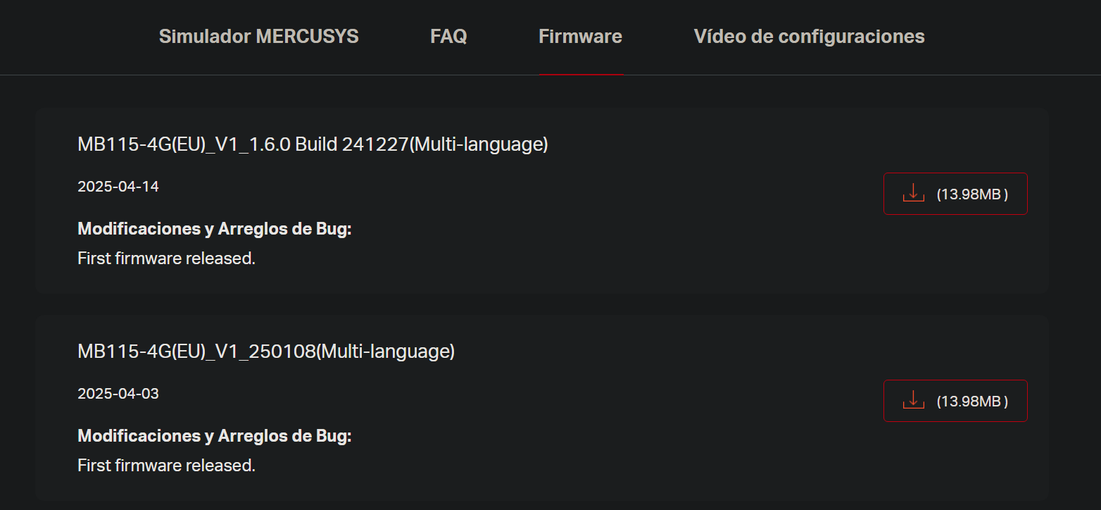 Figure 1: Firmware versions available in the downloads section
After extracting the squashfs filesystem with binwalk (I also took a brief look at the kernel and the bootloader, a U-boot, but they weren’t my main interest) and comparing both versions with diffing tools (meld and diff), I found that the differences between versions were minimal—only a couple of additions in the web page information to identify and support other router models. As they were the same, I went with version 1.6.0.
The first thing I did was to look for the init process (the first userland process that is loaded after the kernel). I found this in /etc/inittab:
 Figure 2: Contents of the inittab file
- First line indicates that the first thing the system will do on boot is execute the /etc/init.d/rcS script (we’ll go to that in a second)
- The second line gives us some interesting info. We have a serial interface ttyS1 in the second serial port of the CPU (first is ttyS0). It has a baud rate of 115200 (pretty standard speed). This will come in handy when we have the physical device to connect to it via UART.
Now, looking at the rcS script we also see some interesting information, I share the most interesting findings here:
- A comment suggesting that the device uses the Mediatek MT7628 (standard in this price range)
1
# 7628 watch dog
- Some security-related info:
1
2
3
4
5
6
7
8
9
10
/bin/mkdir -m 0777 -p /var/https
/bin/mkdir -m 0777 -p /var/lock
/bin/mkdir -m 0777 -p /var/log
[...]

cp -p /etc/passwd.bak /var/passwd
[...]

telnetd
[...]
- Max perms for everyone in a lot of /var directories
- Telnet without args (open console for anyone?)
- The system seems to be restoring the same passwords file at every boot. Let’s have a look at the passwd.bak file:
 Figure 3: Contents of the passwd.bak file
- dropbear: User for the SSH service
- nobody: This user exists for processes that should have minimal privileges. However, here it has UID and GID 0 (0:0), meaning it has root privileges. Very dangerous.
- admin: Even though the name is not root, it acts like it. The password is MD5-crypt ($1) and has no salt.
I cracked the admin password with hashcat using the rockyou.txt wordlist. After a couple of seconds it broke. Guess what, the password is 1234. This may be useful later.
After this initial recon, I decided to wait until I had the router to analyze the firmware that came with it.
PD: At the moment of writing this post I’ve discovered that if you change the language of the firmware download page to English, there are 2 extra firmwares available, both newer than the ones that appeared in the Spanish section. (Pretty odd, huh?)
1. Hardware Analysis
In this section we’ll identify the main components of the router and their functionality.
The first thing I had to do once I got the router was to open it. The device only had 2 little screws in its back.
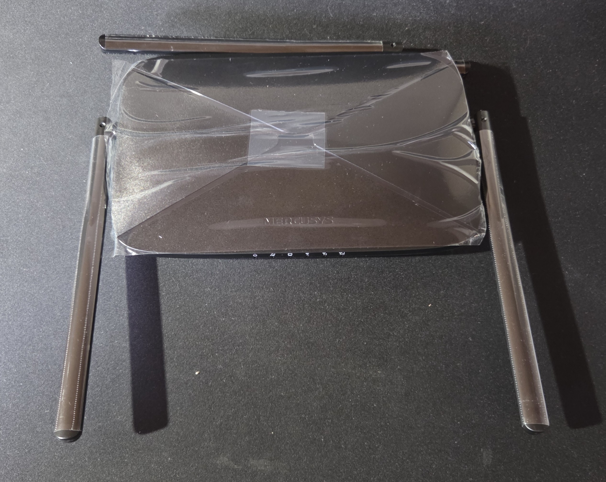 Figure 4: Router front view
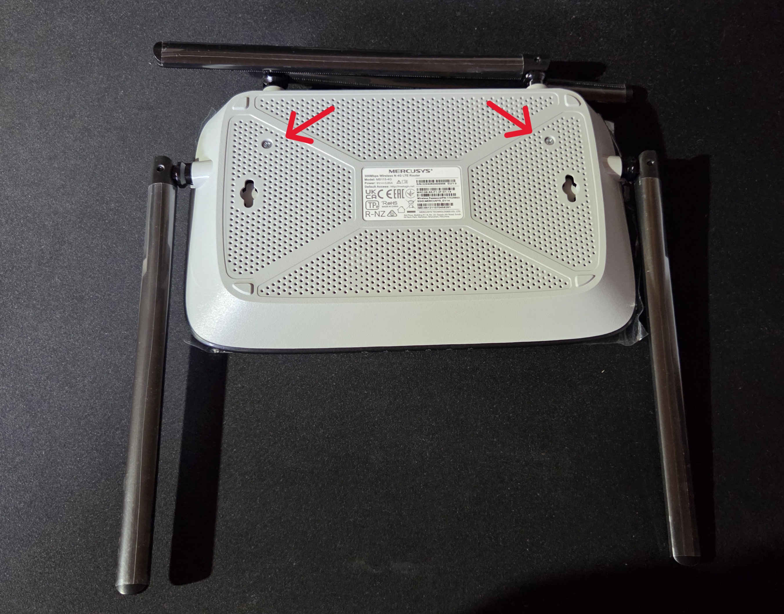 Figure 5: Router back view
After removing them, I used a flat screwdriver to fully open it (I admit it was kind of tricky—maybe I should get a spudger). This is the inside of the device; I’ll explain the components that caught my eye:
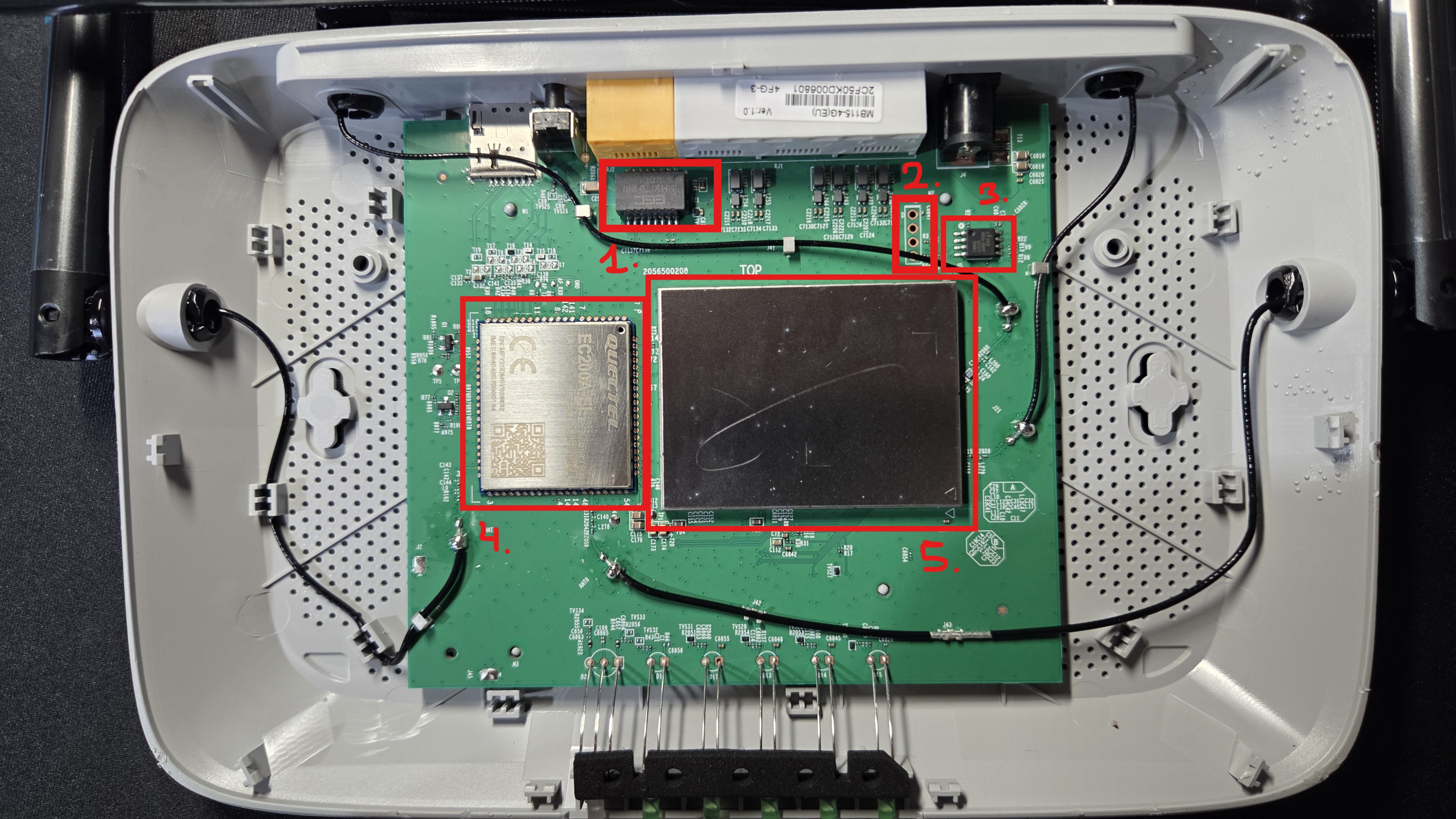 Figure 6: Router internals showing main components
1. Ethernet Transformer:
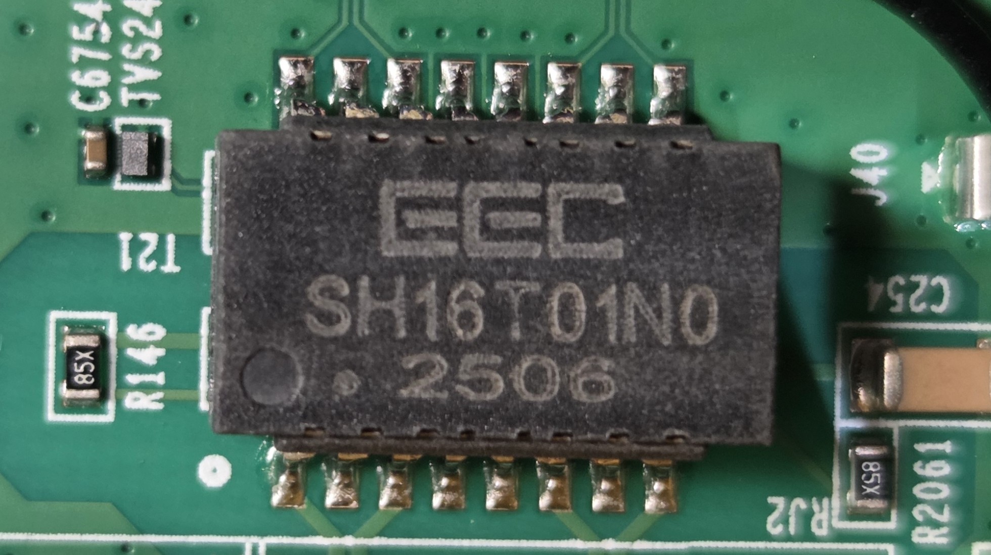 Figure 7: Ethernet transformer component
A magnetic component located immediately behind the RJ45 ports. It provides galvanic isolation. It protects the internal circuitry from voltage spikes on the network cables and filters electromagnetic noise to ensure data integrity over the Ethernet connection.
2. UART (Serial Console Port):
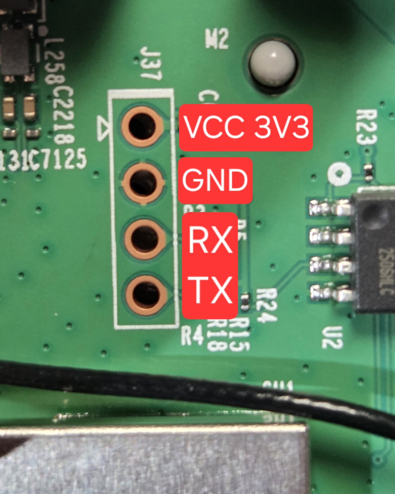 Figure 8: UART pinout identification
The physical “backdoor” for developers. By connecting a USB-to-TTL adapter, we can monitor the kernel boot logs and, if unprotected, drop into a root shell directly. If you want to find more about this protocol, go here: https://www.analog.com/en/resources/analog-dialogue/articles/uart-a-hardware-communication-protocol.html
The UART wasn’t labeled, so I had to identify the different ports using a Voltmeter. First I found GND and then I connected the router to power looking for a port with constant voltage (VCC, operating at 3.3 V) and a fluctuating one (TX).
3. SPI Flash Memory:
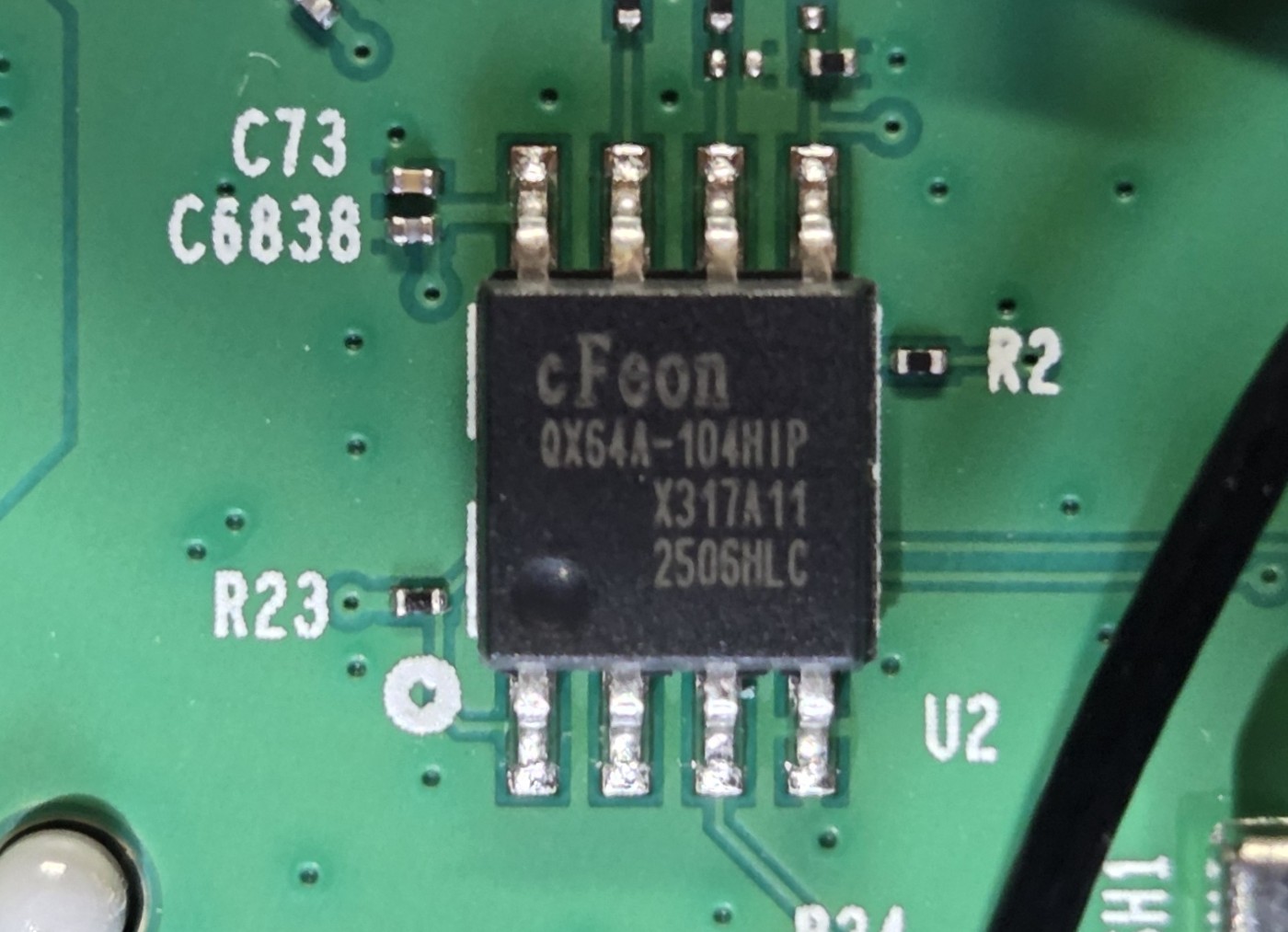 Figure 9: SPI flash memory chip
This is the router’s “hard drive.” It stores the Firmware. It’s our primary target for extracting the firmware dump for static analysis.
4. 4G LTE Module:
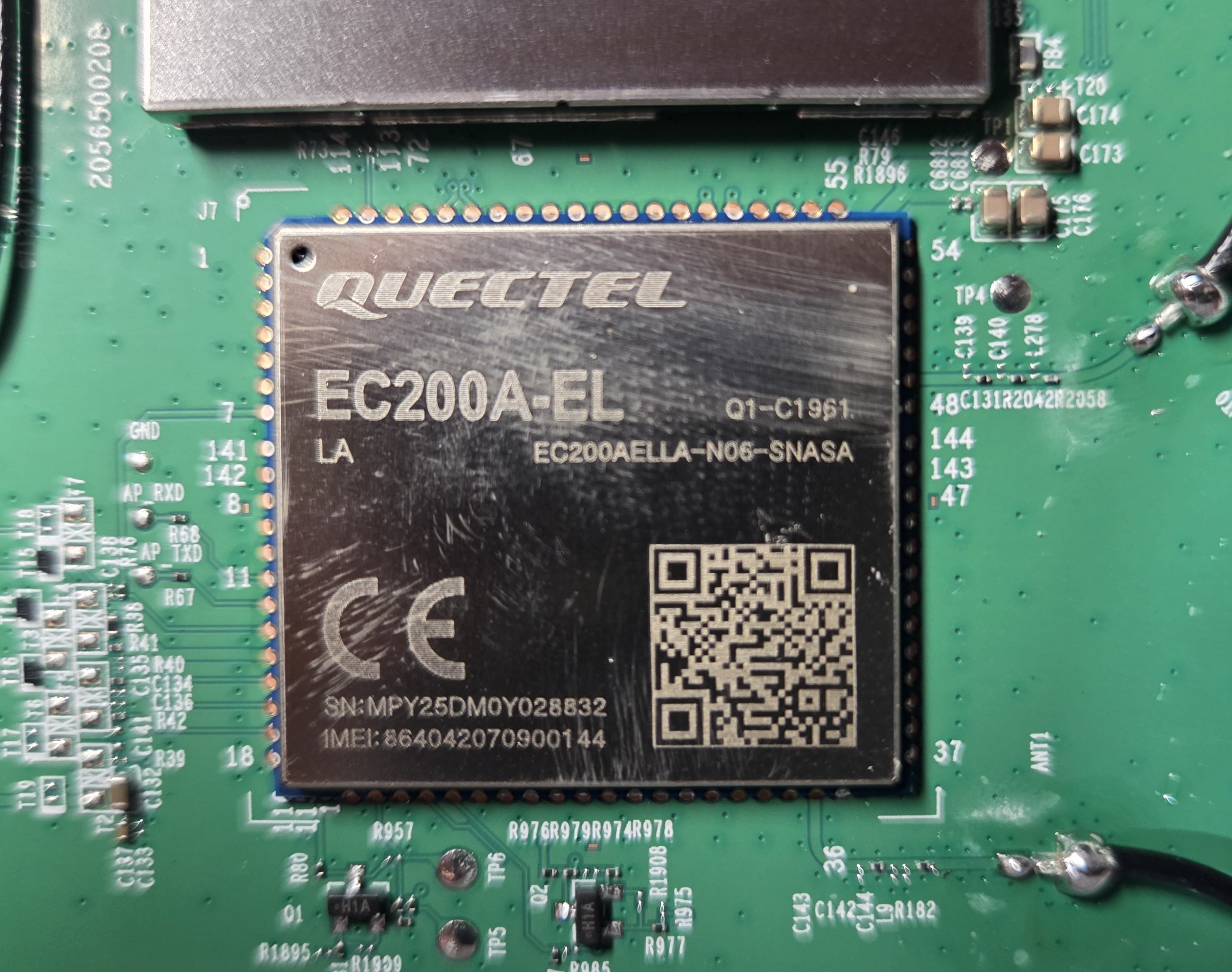 Figure 10: 4G LTE module
A self-contained cellular communication module soldered to the main board. It manages the connection to mobile networks, SIM card authentication, and data transmission.
5. Main EMI Shield (SoC & RAM): An Electromagnetic Interference (EMI) shield. It is a metal cage that covers the most sensitive components. It houses the SoC (System on Chip) and the RAM.
2. Connecting via UART to access the system
Now that we have identified the various components in the PCB, it’s time to come up with a plan to gain a first foothold in the system. As we have discovered a UART interface that seems to be active (because of the test with the voltmeter and the previous firmware reconnaissance) we’ll go with that.
The first thing we need to do is get a good connection to the UART. We can accomplish this in several ways. On this occasion, I decided to solder some pins directly to the interface to use a TTL-to-USB adapter.
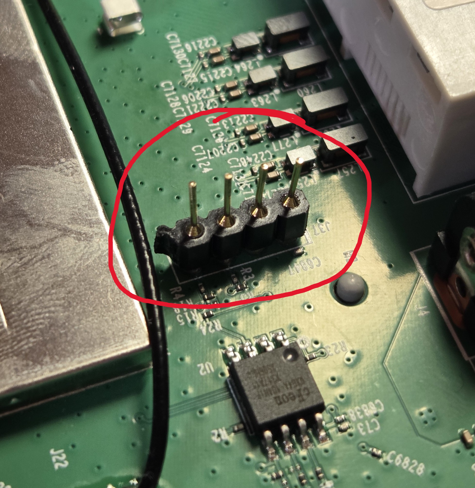 Figure 11: Soldered UART pins for connection
Now we can use the adapter to monitor the bootlogs and interact with the interface. We have to connect the pins properly as shown in the image (notice that VCC is not used, as both the adapter and the PCB have their own power supply). Also remember to change the adapter voltage to 3.3 V, otherwise we could damage some circuit.
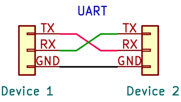 Figure 12: UART connection diagram
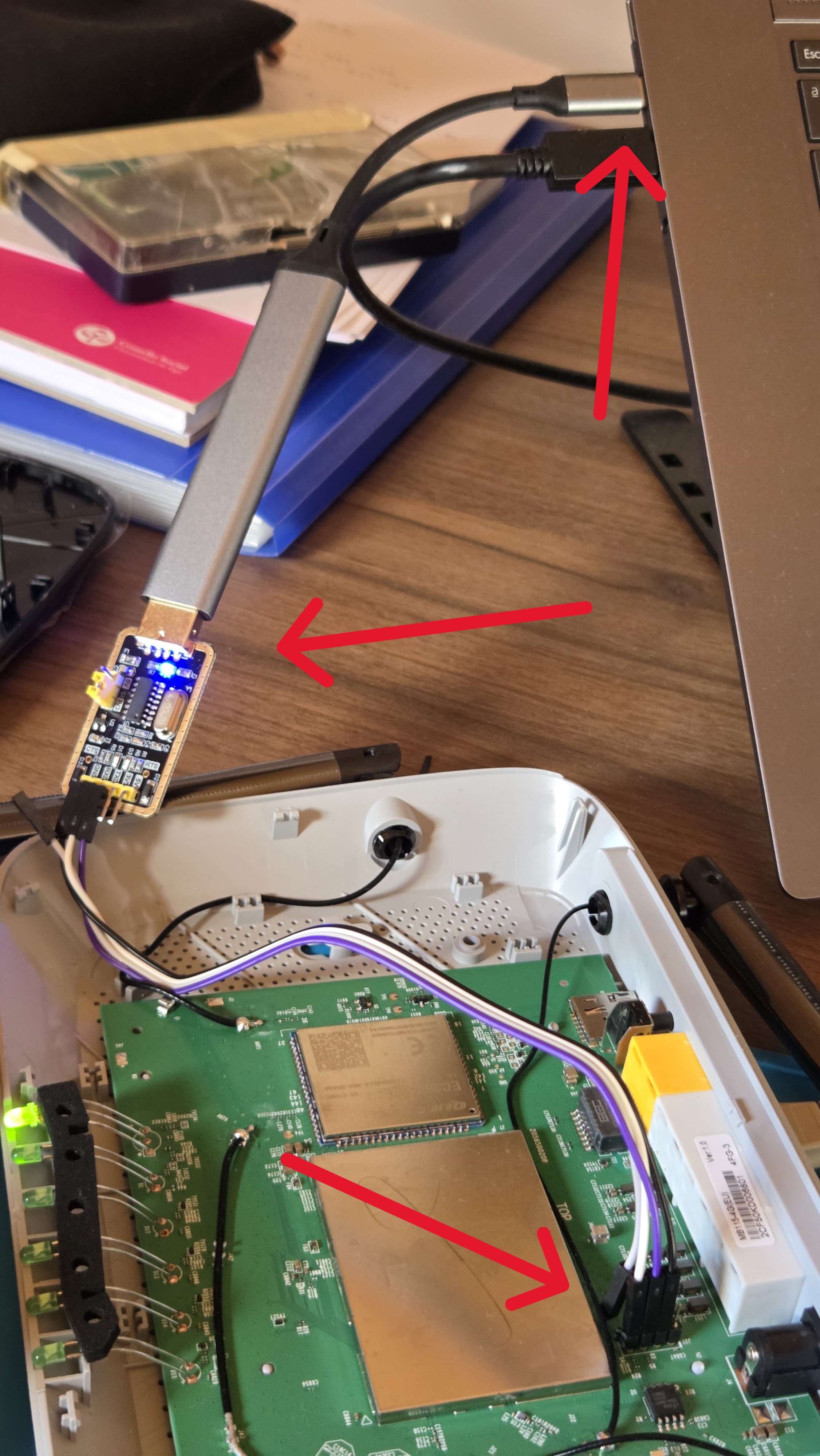 Figure 13: TTL-to-USB adapter
Now we only need to connect the adapter to the computer, identify the device (/dev/ttyUSB0 in my case) and use screen indicating the essential parameters so both devices understand each other.
1
screen /dev/ttyUSB0 115200
I’ll try with a baud rate of 115200 (the one we saw in the inittab file) and the default config. If we see strange symbols instead of legible characters that means that some parameter is wrong. In that case we could use a logic analyzer to try to decipher the way the protocol is sending the information.
We plug in the router and see boot information come across the screen, confirming that the parameters are right and we are receiving the information properly. We save all the boot logs in a file to look at them later.
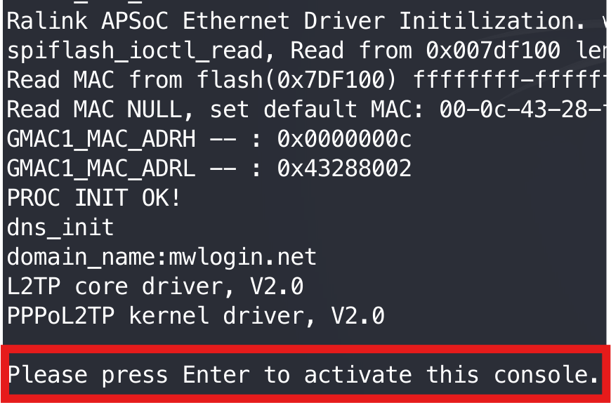 Figure 14: Boot logs showing console prompt
Among all the boot logs, we can see a message asking us to press the ENTER key to activate the console. Then it asks us for a username and a password. If we try users like root or admin without a valid password we cannot login.
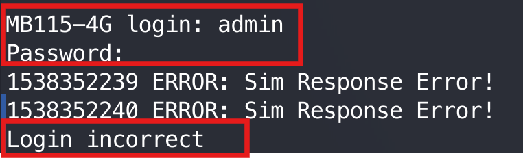 Figure 15: Failed login attempt
Let’s try with the credentials we saw in the passwd.bak file:
 Figure 16: Successful root login
The credentials are valid!! Now we have a shell as root.
3. Dumping the firmware
Now that we have complete access to the system, I want to see if I can extract all the firmware without having to use an EEPROM reader. I’m too lazy for that.
Luckily for us, if we type in busybox –list we can see all the utilities available inside busybox. Among them we have tftp. We can use it to dump all the firmware to our local machine without having to connect anything to the PCB.
IMPORTANT: Notice that extracting the firmware via tftp is the same as extracting it with an EEPROM reader. In either case we are not extracting the contents of the RAM (dynamically created under the /var directory). We don’t need to extract them as we have root access to the device in case we need to interact with them later. After this clarification, let’s continue with the extraction.
The only thing we need is a tftp server running on the host (I used atftpd) and a connection to one of the router LAN ports.
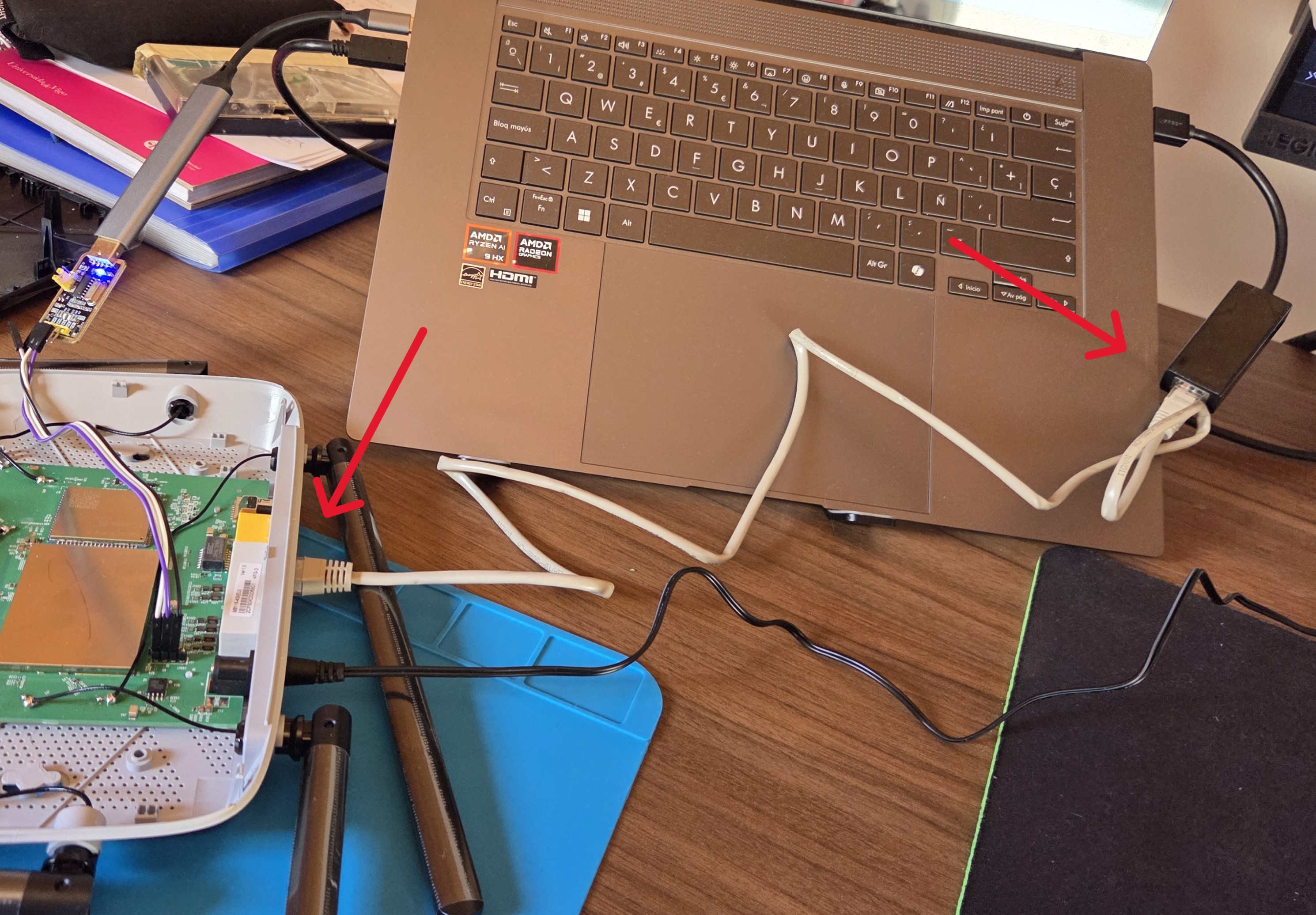 Figure 17: Final setup with UART and LAN connection
Now let’s enumerate all the system partitions (present in /proc/mtd):
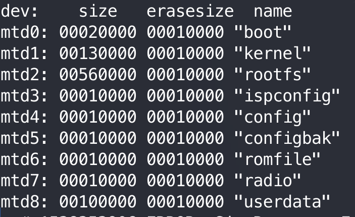 Figure 18: Flash memory partitions listing
With all this information, we turn up the tftp server on our machine and run the following script on the router.
1
2
3
4
5
6
7
8
9
cd /tmp
for i in 0 1 2 3 4 5 6 7 8; do
    echo "Extracting mtd$i..."
    cat /dev/mtd$i > mtd$i.bin
    #The IP below is the one the router gave to my computer
    tftp -p -l mtd$i.bin -r mtd$i.bin 192.168.1.101
    rm mtd$i.bin
done
echo "DONE!"
And with that, we have just dumped all the flash memory of the router. (I would recommend comparing the MD5 hashes of the dumped memory to ensure no information loss).
Recap and next steps
This is the end of this first part of the blog series. Here’s what we’ve accomplished:
Security issues found so far:
- Weak default credentials (admin:1234)
- Unsalted MD5 password hashes
- User “nobody” running with UID 0 (root privileges)
- World-writable directories (777 permissions)
In the upcoming posts, we will dive into the root filesystem looking for potential vulnerabilities in the main binaries, analyze the web interface for security flaws, and attempt to find exploitable vulnerabilities.
That’s all for now. Hope you found this useful! And remember,